SMA Routes & Nesting Default parameters
Are there any parameters to control how a default polyline route is created when using the Solid Model Analyzer? We are having issues when we place our SMA parts on a nest, the routes are not picked up correctly and instead of converting the border routes to one path they remain as separate route conditions. Doing some trial and error I figured out that it is because the first route segment stops 0.1mm outside of the part border before it continues the correct path; the last segment does the same. If we can modify this to be a different value than 0.1mm the route works and is nested properly.
Some visuals may help explain. We started with a solid diewall stud and converted it using SMA.
Here is the route generated for our rail notch, including "mouse ears":
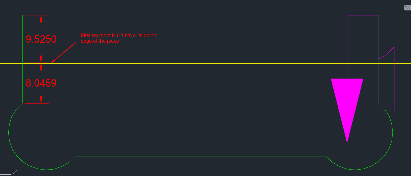
It is hard to see here but the dimension between the border (yellow) and the first segment (9.525mm) is 0.1mm
This is an iso view of what the route looks like on our CNC software:
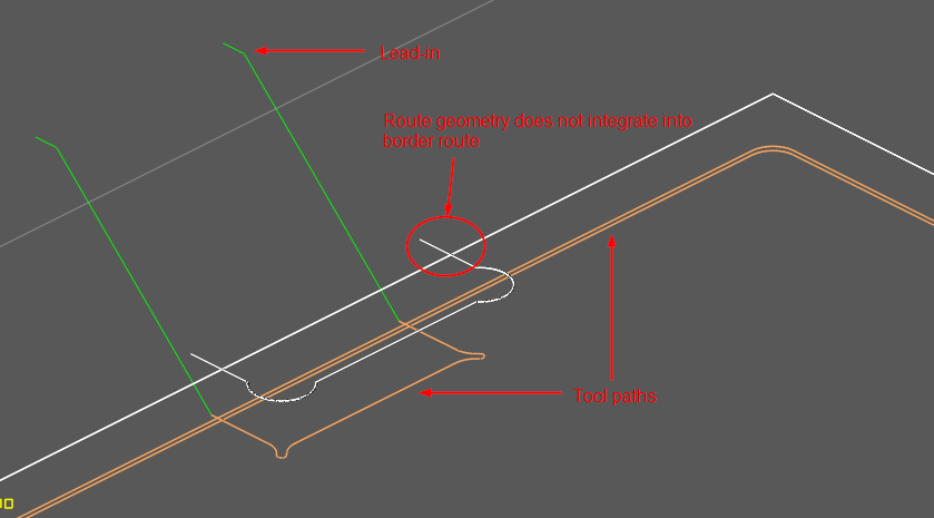
The white lines represent the geometry that our tool file produces based on the default SMA results and they are separate actions and tool paths
As a test, I modifed the default 0.1mm offset into a few scenarios:
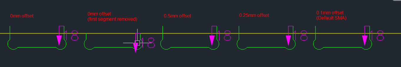
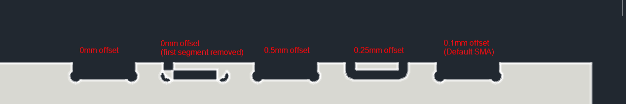
And the resulting nest:

So have no offset to the routes OR having the offset greater than 0.5mm works correctly but anything inbetween, where the SMA puts the offset, does not process correctly.
So if anyone has any insight into how we can change the default SMA parameters, or another possible solution to have these routes calculated correctly I would greatly appreciate it.
Bonus Image, The 3D visuals does some funky stuff on a couple of these tests. The 0.25mm offset route is particularly puzzling:
Topic Participants
Micah Hesketh
Clay S.
RCL_SWI
Jacob Scianna
Shawn Golden | Quality Assurance Specialist
MVU eLearning
Grow Your Knowledge
Follow along with RJ as he takes you on a journey to build your foundational knowledge of Toolbox.
Follow us on: