Solid Model Parts Need To Reference Perpendicular Corners
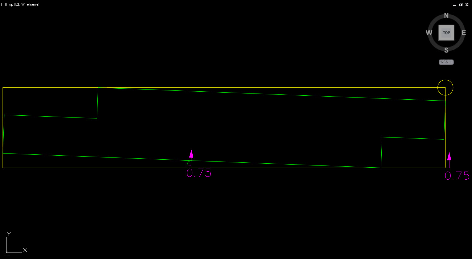
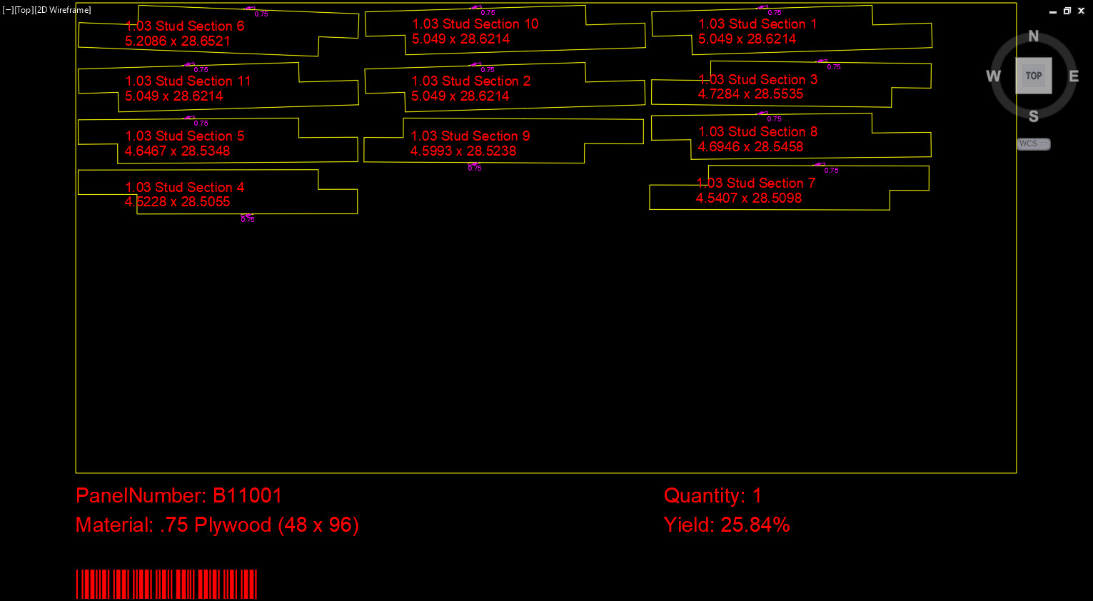
So, when creating a product like a curved die wall, where the stud profile has a toe kick notch, and possibly a counter notch, some of the parts will nest slightly rotated - this is caused because the program is trying to figure out how to cut the stud shape out of a part, which is rotated if you look at the part drawn in 2D. Depending on the product, these types of parts (not always studs) may be grain directional. If the analyzation of parts isn't looking to perpendicular corners first, then that means user are going to have to rotate a lot of parts in the nest to get the grain fixed. See the images below.
Stud part drawn in 2D:
Studs nested:
I'm not a programmer, so I'm not going to pretend this would be an easy fix. But having to manually rotate parts in the nest means more time spent creating work orders. I'd love to hear if this is something that could be achieved - this would make those tools almost fool proof.
James Drury
James Drury
Technology Advocate
MICROVELLUM SOFTWARE
VimeoTopic Participants
James Drury
Rod Host
Ryan Kinninment
Clay S.
David Sumner
MVU eLearning
Grow Your Knowledge
Follow along with RJ as he takes you on a journey to build your foundational knowledge of Toolbox.
Follow us on: