MIRROR Command
Creates a mirrored copy of selected objects.
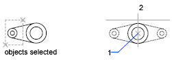
You can create objects that represent half of a drawing, select them, and mirror them across a specified line to create the other half.

By default, when you mirror a text object, the direction of the text is not changed. Set the MIRRTEXT system variable to 1 if you do want the text to be reversed.
The following prompts are displayed:
Select Objects
Use an object selection method to select the objects to be mirrored. Press Enter to finish.
Specify First Point, Second Point of Mirror Line
The two specified points become the endpoints of a line about which the selected objects are mirrored. For mirroring in 3D, this line defines a mirroring plane perpendicular to the XY plane of the user coordinate system (UCS) containing the mirror line.
Erase Source Objects
Determines whether the original objects are erased or retained after mirroring them.

Powered by AutoCAD®
Related Articles
Microvellum Commands vs AutoCAD Commands
Microvellum AC, as a software based in AutoCAD, possesses the full range of AutoCAD commands for use in accessing AutoCAD functions, such as drawing shapes, opening menus, altering the dimensions of polylines, etc. However, it should be noted that ...Basic 2D Commands
Basic 2D Commands To execute an AutoCAD command, type the command (or quick-key) in the command line. The command line is located at the bottom of the drawing area. Some commands require additional steps, or subcommands, the next step for the command ...Tutorial: Adding a Microvellum Command Button
To minimize the number of clicks necessary when using Microvellum software, we are providing this article as a tutorial for setting up your Microvellum Tool Strip with command buttons that activate the command directly without clicking several ...MIRROR3D Command
Creates a mirrored copy of selected 3D objects across a mirroring plane. You can specify the mirroring plane by aligning the objects with a specified plane or by specifying three points. For Example: It is recommended that you use the gizmos ...AutoCAD Keyboard Commands
Learning how to use AutoCAD keyboard commands can help you work faster and improve your efficiency. This article lists the abbreviated commands that can be used in AutoCAD (Toolbox). Toggle General Features Ctrl+G Toggle Grid Ctrl+E Cycle isometric ...
Recent Articles
Microvellum Release Notes | Build 26.1.0723.641
The following release notes apply to Microvellum build 26.1.0723.641. Function UI Update The Function Arguments interface has received a major visual overhaul to improve the usability, clarity, and visibility of several elements. Input fields are now ...Microvellum Release Notes | Build 26.1.0702.641
Dark Mode Fig. 1: The MV Palette in Dark Mode. To enhance the user experience when working within Microvellum, a new Dark Mode setting has been added to the software. Enabling this will apply a dark theme to most interfaces, allowing for a greater ...Microvellum Foundation Library Release Notes | Build 26.0630
Additions: Added new Fixture product Die Wall Advanced. This product takes the legacy Die Wall products to a new level. More features and advanced parametric abilities: Up to five individual unique subassembly segments, widths controlled via ...Microvellum Foundation Library Release Notes | Build 26.0527
The following release notes apply to the Microvellum Foundation Library build 26.0527. Additions Added new features for the Wood Drawer Box to have reduced sides, sub front, or back. Added 3 new global and subassembly prompts: “Wood Drawer Side ...Microvellum Release Notes | Build 26.1.0529.641
The following release notes apply to Microvellum build 26.1.0529.641. BSB Docking Size Fix An issue was reported to be occurring in Microvellum BSB 2026: when adjusting the size of a docked Microvellum palette, users found that the palette would ...