3DFACE Command
Creates a three-sided or four-sided surface in 3D space.
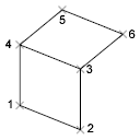
After entering the last two points for a 3D face, the command repeats automatically using the two points as the first two points of the next 3D face. For example:
The following prompts are displayed:
First Point
Defines the start point for the 3D surface. After entering the first point, enter the remaining points in a natural clockwise or counterclockwise order to create a normal 3D face. If you locate all four points on the same plane, a planar face is created that is similar to a region object. When you shade or render the object, planar faces are filled.
Second Point
Defines the second point for the 3D surface.
Third Point
Defines the third point for the 3D surface.
Fourth Point
Defines the fourth point for the 3D surface.
The Third point and Fourth point prompts are repeated until you press Enter. Specify points 5 and 6 at these repeating prompts. When you finish entering points, press Enter.
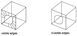
Invisible
Controls which edges of a 3D face are visible, allowing for accurate modeling of objects with holes. Entering i or invisible before the first point of an edge makes the edge invisible.
The invisible specification must precede any object snap modes, XYZ filters, or coordinate input for that edge. You can create a 3D face in which all edges are invisible. Such a face is a phantom; it does not appear in wireframe presentations but can hide material in line drawings. 3D faces do appear in shaded renderings.
You can combine 3D faces to model complex 3D surfaces.
Powered by AutoCAD®
Related Articles
3DPOLY Command
Creates a 3D polyline. A 3D polyline is a connected sequence of straight line segments created as a single object. 3D polylines can be non-coplanar; however, they cannot include arc segments. The following prompts are displayed: Start Point of ...ACTBASEPOINT Command
Inserts a base point or base point prompt in an action macro. As you record an action macro, you can use this command to insert a prompt for base point input. During playback, the macro pauses to display the prompt and does not continue until a ...PSPACE Command
In a layout, switches from model space in a layout viewport to paper space. As part of designing a layout, you can create objects in paper space. Typically, you insert a title block (see INSERT) and create layout viewports (see VPORTS), which can ...OFFSET Command
Creates concentric circles, parallel lines, and parallel curves. You can offset an object at a specified distance or through a point. After you offset objects, you can trim and extend them as an efficient method to create drawings containing many ...DRAWORDER Command
Changes the draw order of images and other objects. Several options are available that control the order in which overlapping objects are displayed. In addition to the DRAWORDER command, the TEXTTOFRONT command brings all text, dimensions, or ...
Recent Articles
Microvellum Release Notes | Build 26.1.0723.641
The following release notes apply to Microvellum build 26.1.0723.641. Function UI Update The Function Arguments interface has received a major visual overhaul to improve the usability, clarity, and visibility of several elements. Input fields are now ...Microvellum Release Notes | Build 26.1.0702.641
Dark Mode Fig. 1: The MV Palette in Dark Mode. To enhance the user experience when working within Microvellum, a new Dark Mode setting has been added to the software. Enabling this will apply a dark theme to most interfaces, allowing for a greater ...Microvellum Foundation Library Release Notes | Build 26.0630
Additions: Added new Fixture product Die Wall Advanced. This product takes the legacy Die Wall products to a new level. More features and advanced parametric abilities: Up to five individual unique subassembly segments, widths controlled via ...Microvellum Foundation Library Release Notes | Build 26.0527
The following release notes apply to the Microvellum Foundation Library build 26.0527. Additions Added new features for the Wood Drawer Box to have reduced sides, sub front, or back. Added 3 new global and subassembly prompts: “Wood Drawer Side ...Microvellum Release Notes | Build 26.1.0529.641
The following release notes apply to Microvellum build 26.1.0529.641. BSB Docking Size Fix An issue was reported to be occurring in Microvellum BSB 2026: when adjusting the size of a docked Microvellum palette, users found that the palette would ...