3DSCALE Command
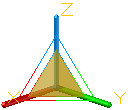
In a 3D view, displays the 3D Scale gizmo to aid in resizing 3D objects.
With the 3D Scale gizmo, you can resize selected objects and sub-objects along an axis or plane, or resize the objects uniformly.
The 3D Scale Gizmo shortcut menu offers options for aligning, moving, or changing to another gizmo.
The following prompts are displayed:
Select Objects
Specifies the objects to be scaled.
Specify Base Point
Specifies the base point for the scaling.
Pick a Scale Axis or Plane
Specifies whether the object is scaled uniformly or only along a specific axis or plane. You have the following choices:
- Scale Uniformly. Click the area closest to the vertex of the 3D Scale gizmo. The interior region of all axes of the gizmo is highlighted.
- Constrain the Scale to a Plane. Click between the parallel lines between the axes that define the plane. This option is only available for meshes, not solids or surfaces.
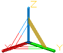
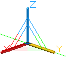
- Constrain the Scale to an Axis. Click the axis. This option is only available for meshes, not solids or surfaces.
Specify Scale Factor
Specifies the amount of change. Drag to dynamically modify the size of the selected objects or enter a scale value. For example, enter 2 to double the size of the selection.
Copy
Creates and scales a copy of the selected objects.
Reference
Sets a scale based on a ration.
- Reference Length. Sets the relative amount that represents the current size in the scale ration.
- New Length. Sets the relative value used to calculate the new size. For example, if the reference length is 1 and the new length is 3, the size of the selected objects is tripled.
- Points. Specifies the relative value used to calculate the new size based on two points that you specify.
Powered by AutoCAD®
Related Articles
3DPOLY Command
Creates a 3D polyline. A 3D polyline is a connected sequence of straight line segments created as a single object. 3D polylines can be non-coplanar; however, they cannot include arc segments. The following prompts are displayed: Start Point of ...ACTBASEPOINT Command
Inserts a base point or base point prompt in an action macro. As you record an action macro, you can use this command to insert a prompt for base point input. During playback, the macro pauses to display the prompt and does not continue until a ...PSPACE Command
In a layout, switches from model space in a layout viewport to paper space. As part of designing a layout, you can create objects in paper space. Typically, you insert a title block (see INSERT) and create layout viewports (see VPORTS), which can ...OFFSET Command
Creates concentric circles, parallel lines, and parallel curves. You can offset an object at a specified distance or through a point. After you offset objects, you can trim and extend them as an efficient method to create drawings containing many ...DRAWORDER Command
Changes the draw order of images and other objects. Several options are available that control the order in which overlapping objects are displayed. In addition to the DRAWORDER command, the TEXTTOFRONT command brings all text, dimensions, or ...
Recent Articles
Microvellum Release Notes | Build 26.1.0723.641
The following release notes apply to Microvellum build 26.1.0723.641. Function UI Update The Function Arguments interface has received a major visual overhaul to improve the usability, clarity, and visibility of several elements. Input fields are now ...Microvellum Release Notes | Build 26.1.0702.641
Dark Mode Fig. 1: The MV Palette in Dark Mode. To enhance the user experience when working within Microvellum, a new Dark Mode setting has been added to the software. Enabling this will apply a dark theme to most interfaces, allowing for a greater ...Microvellum Foundation Library Release Notes | Build 26.0630
Additions: Added new Fixture product Die Wall Advanced. This product takes the legacy Die Wall products to a new level. More features and advanced parametric abilities: Up to five individual unique subassembly segments, widths controlled via ...Microvellum Foundation Library Release Notes | Build 26.0527
The following release notes apply to the Microvellum Foundation Library build 26.0527. Additions Added new features for the Wood Drawer Box to have reduced sides, sub front, or back. Added 3 new global and subassembly prompts: “Wood Drawer Side ...Microvellum Release Notes | Build 26.1.0529.641
The following release notes apply to Microvellum build 26.1.0529.641. BSB Docking Size Fix An issue was reported to be occurring in Microvellum BSB 2026: when adjusting the size of a docked Microvellum palette, users found that the palette would ...