ARC Command
Creates an arc.
To create an arc, you can specify combination of center, endpoint, start point, radius, angle, chord length, and direction values. Arcs are drawn in a counterclockwise direction by default. Hold down the Ctrl keys as you drag to draw in a clockwise direction.
The following options are available:
Start Point
Draws an arc using three specified points on the arc's circumference. The first point is the start point (1).

If you press ENTER without specifying a point, the endpoint of the last drawn line or arc is used and you are immediately prompted to specify the endpoint of the new arc. This creates an arc tangent to the last drawn line, arc, or polyline.
Second Point
Specify the second point (2) is a point on the circumference of the arc.
End Point
Specify the final point (3) on the arc.

You can specify a three-point arc either clockwise or counterclockwise.
Center
Starts by specifying the center of the circle of which the arc is a part.
Start Point
Specify the start point of the arc.
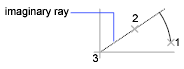
End Point
Using the center point (2), draws an arc counterclockwise from the start point (1) to an endpoint that falls on an imaginary ray drawn from the center point through the third point (3).

The arc does not necessarily pass through this third point, as shown in the illustration.
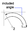
Angle
Draws an arc counterclockwise from the start point (1) using a center point (2) with a specified included angle. If the angle is negative, a clockwise arc is drawn.
Chord Length
Draws either a minor or a major arc based on the distance of a straight line between the start point and endpoint.
If the chord length is positive, the minor arc is drawn counterclockwise from the start point. If the chord length is negative, the major arc is drawn counterclockwise.

End
Starts by specifying the endpoint of the arc.
Center Point
Draws an arc counterclockwise from the start point (1) to an endpoint that falls on an imaginary ray drawn from the center point (3) through the second point specified (2).
Angle
Draws an arc counterclockwise from the start point (1) to an endpoint (2), with a specified included angle. If the angle is negative, a clockwise arc is drawn.
Included Angle
Enter an angle in degrees or specify an angle by moving the pointing device counterclockwise.

Direction
Begins the arc tangent to a specified direction. It creates any arc, major or minor, clockwise or counterclockwise, beginning with the start point (1), and ending at an endpoint (2). The direction is determined from the start point.

Radius
Draws the minor arc counterclockwise from the start point (1) to the endpoint (2). If the radius is negative, the major arc is drawn.

Center
Specifies the center of the circle of which the arc is a part.
Start Point
Specify start point of an arc.
End Point
Draws an arc counterclockwise from the start point (1) to an endpoint that falls on an imaginary ray drawn from the center point (2) through a specified point (3).

Angle
Draws an arc counterclockwise from the start point (1) using a center point (2) with a specified included angle. If the angle is negative, a clockwise arc is drawn.

Chord Length
Draws either a minor or a major arc based on the distance of a straight line between the start point and endpoint.
If the chord length is positive, the minor arc is drawn counterclockwise from the start point. If the chord length is negative, the major arc is drawn counterclockwise.

Tangent to Last Line, Arc, or Polyline
Draws an arc tangent to the last line, arc, or polyline drawn when you press ENTER at the first prompt.
End Point of Arc
Specify a point (1).
Powered by AutoCAD®
Related Articles
3DPOLY Command
Creates a 3D polyline. A 3D polyline is a connected sequence of straight line segments created as a single object. 3D polylines can be non-coplanar; however, they cannot include arc segments. The following prompts are displayed: Start Point of ...FILLET Command
Rounds the edges of two 2D objects. A round or fillet is an arc that is created tangent between two 2D objects. A fillet can be created between two objects of the same or different object types: 2D polylines, arcs, circles, ellipses, elliptical ...BREAK Command
Breaks the selected object between two points. You can create a gap between two specified points on an object, breaking it into two objects. If the points are off of an object, they are automatically projected on to the object. BREAK is often used ...PRESSPULL Command
Dynamically modifies objects by extrusion and offset. Get visual feedback as you move the cursor after selecting a 2D object, an area formed by a closed boundary or a 3D solid face. The press or pull behavior responds to the type of object you ...EXTRUDE Command
Creates a 3D solid from an object that encloses an area, or a 3D surface from an object with open ends. Objects can be extruded orthogonally from the plane of the source object, in a specified direction, or along a selected path. You can also ...
Recent Articles
Microvellum Release Notes | Build 26.1.0723.641
The following release notes apply to Microvellum build 26.1.0723.641. Function UI Update The Function Arguments interface has received a major visual overhaul to improve the usability, clarity, and visibility of several elements. Input fields are now ...Microvellum Release Notes | Build 26.1.0702.641
Dark Mode Fig. 1: The MV Palette in Dark Mode. To enhance the user experience when working within Microvellum, a new Dark Mode setting has been added to the software. Enabling this will apply a dark theme to most interfaces, allowing for a greater ...Microvellum Foundation Library Release Notes | Build 26.0630
Additions: Added new Fixture product Die Wall Advanced. This product takes the legacy Die Wall products to a new level. More features and advanced parametric abilities: Up to five individual unique subassembly segments, widths controlled via ...Microvellum Foundation Library Release Notes | Build 26.0527
The following release notes apply to the Microvellum Foundation Library build 26.0527. Additions Added new features for the Wood Drawer Box to have reduced sides, sub front, or back. Added 3 new global and subassembly prompts: “Wood Drawer Side ...Microvellum Release Notes | Build 26.1.0529.641
The following release notes apply to Microvellum build 26.1.0529.641. BSB Docking Size Fix An issue was reported to be occurring in Microvellum BSB 2026: when adjusting the size of a docked Microvellum palette, users found that the palette would ...