Configuration Editor: Solid Analyzation Options
The Solid Analyzation tab contains settings that determine the procedure for analyzing a 3D solid model to convert it into a Microvellum product.
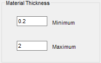
Material Thickness
Minimum and maximum thickness used to determine if a 3D model's thickness is within the acceptable range for analyzation.
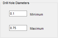
Drill Hole Diameters
Minimum and Maximum drill hole diameter used to determine if a 3D solid with drill holes is within the acceptable range for analyzation.
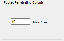
Pocket Penetrating Cutouts
If a cutout machining sequence falls within the specified area, then the machining will use a pocket-machining token. Otherwise, machining uses a cutout machine token.
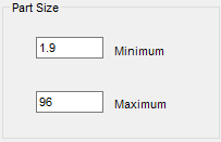
Part Size
Minimum and Maximum part length used to determine if a 3D solid with drill holes is within the acceptable range for analyzation.
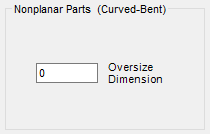
Nonplanar Parts (Curved-Bent)
Part oversize adjustment for curved and bent parts.
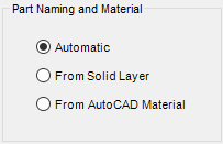
Part Naming and Material
Determines the naming conventions for parts that the Solid Model Analyzer successfully analyzed.
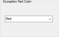
Exception Part Color
Visual indicator for parts that did not successfully pass through the Solid Model Analyzer. The 3D representation of the part is set to the selected color upon analysis results if part analyzation is unsuccessful.
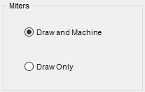
Miters
Determines whether miters are "draw only" or "draw and machine."
Tool Selection
A visual reminder of where to set the tool preferences for solids machining.
Related Articles
Solid Model Analyzer - Solid Analyzation Tab
You will find these properties on the Solid Analyzation tab of the Microvellum Options page. Each section below contains the properties listed. Fig. 1 – Solid Analyzation Properties Material Thickness Section Fig. 2 – Material Thickness Options ...Overview: Configuration Editor (Options) Interface
The Configuration Editor (Options) Interface for Microvellum Toolbox is accessible from the Toolbox Setup menu. Using the options contained within, you'll configure general system settings, set up the optimization software you use, set up tool files, ...Solid Analyzation Settings
Solid Analyzation Settings To access the settings for solid analyzation, open the Toolbox Options (Toolbox Setup -> Options) and select the Solid Analyzation tab. Material Thickness – Allows you to specify minimum and maximum thicknesses for parts. ...Configuration Editor: Processing Options
This article provides an overview of the options and settings available on the Processing tab of the Configuration Editor (Options) Interface. For a complete list of available tabs and options visit Overview: Configuration Editor (Options) Interface. ...Configuration Editor: General Options
This article provides an overview of the options and settings available on the General tab of the Configuration Editor (Options) Interface. For a complete list of available tabs and options visit Overview: Configuration Editor (Options) Interface. ...
Recent Articles
Microvellum Release Notes | Build 26.1.0723.641
The following release notes apply to Microvellum build 26.1.0723.641. Function UI Update The Function Arguments interface has received a major visual overhaul to improve the usability, clarity, and visibility of several elements. Input fields are now ...Microvellum Release Notes | Build 26.1.0702.641
Dark Mode Fig. 1: The MV Palette in Dark Mode. To enhance the user experience when working within Microvellum, a new Dark Mode setting has been added to the software. Enabling this will apply a dark theme to most interfaces, allowing for a greater ...Microvellum Foundation Library Release Notes | Build 26.0630
Additions: Added new Fixture product Die Wall Advanced. This product takes the legacy Die Wall products to a new level. More features and advanced parametric abilities: Up to five individual unique subassembly segments, widths controlled via ...Microvellum Foundation Library Release Notes | Build 26.0527
The following release notes apply to the Microvellum Foundation Library build 26.0527. Additions Added new features for the Wood Drawer Box to have reduced sides, sub front, or back. Added 3 new global and subassembly prompts: “Wood Drawer Side ...Microvellum Release Notes | Build 26.1.0529.641
The following release notes apply to Microvellum build 26.1.0529.641. BSB Docking Size Fix An issue was reported to be occurring in Microvellum BSB 2026: when adjusting the size of a docked Microvellum palette, users found that the palette would ...