Drawing Polylines
Draw polylines with straight or curved segments. Define the width for the polyline segments and taper the width across the segment. Draw polygons specifying the number of sides and size.
Draw a Polyline with Straight Segments
- Click Home tabDraw panelPolyline.
 (Find)
 - Specify the first point of the polyline.
- Specify the endpoint of the first segment.
- Continue specifying segment endpoints as needed.
- Press Enter to end or enter c to close the polyline.
 To start a polyline at the endpoint of the last polyline drawn, start the command again and press Enter at the Specify Start Point prompt.
Draw a Wide Polyline
- Click Home tabDraw panelPolyline. (Find)
- Specify the first point of the polyline.
- Enter w (Width)
- Enter the starting width of the segment.
- Specify the ending width of the segment using one of the following methods:
- To create a segment of equal width, press Enter.
- To create a tapering or increasing segment, enter a different width.
- Specify the endpoint of the segment.
- Continue specifying segment endpoints as needed.
- Press Enter to end or enter c to close the polyline.
Draw a Polyline with Straight and Curved Segments
- Click Home tabDraw panelPolyline. (Find)
- Specify the first point of the polyline.
- Specify the endpoint of the first segment.
- Switch to Arc mode by entering an (Arc) at the Command prompt.
- Return to Line mode by entering L (Line).
- Specify additional segments as needed.
- Press Enter to end or enter c to close the polyline.
Draw a Rectangle
- Click Home tabDraw panelRectangle.
 (Find)
 - Specify the first corner of the rectangle.
- Specify the diagonal corner of the rectangle.
Draw a Polygon
- Click Home tabDraw panelPolygon.
 (Find)
 - Enter the number of sides.
- Specify the center of the polygon.
- Do one of the following:
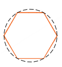
Enter "I" to specify a polygon inscribed within a circle.
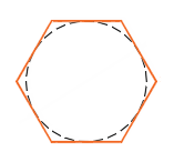
Enter c to specify a polygon circumscribed about a circle.
Enter the radius length.
Draw a Polygon by Specifying One Edge
Click Home tabDraw panelPolygon. (Find)
(Find)Enter the number of sides.
Enter "E" (Edge).
Specify the start point for one polygon segment.
Specify the endpoint of the polygon segment.

Draw a Boundary Polyline
- Click Home tabDraw panelBoundary.
 (Find)
 - In the Boundary Creation dialog box, Object Type list, select Polyline.
- Click Pick Points.
 Specify points within each area to form a boundary polyline for each.
 - Note: Each area must be enclosed.
- Press Enter to create the boundary polylines and end the command.
Related Articles
POLYGON Command
Creates an equilateral closed polyline. You specify the number of sides of the polygon and whether it is inscribed or circumscribed. The following prompts are displayed: Number of Sides Specifies the number of sides in the polygon (3-1024). ...Modifying Polylines
Stretch a Segment You can select a grip to make changes directly. Select the polyline to display its grips. Select a grip and drag it to the new location. Menu Options for Modifying Polylines Several options become available when you select a ...Drawing Tools
Drawing Tools To access the Drawing Tools, click on the Draw tab, and then select the Drawing Tools tab. The Drawing Tools interface has three tabs on the right side: Common Commands, Common Text, Common Blocks. Common Commands Tab The Common ...Understanding Drawing Tabs
Located at the bottom of the drawing area are tabs that allow you to switch between the Model tab and other layout tabs. While working in the drawing environment, you will need to have the Model tab selected. Selecting any other tab will bring you to ...Drawing Sections
Drawing Sections To draw sections of products, click on the Draw Product Sections icon and select a product. The Product Sections window will allow you to select which type of section to draw and set up specific options for how the section will be ...
Recent Articles
Microvellum Release Notes | Build 26.1.0723.641
The following release notes apply to Microvellum build 26.1.0723.641. Function UI Update The Function Arguments interface has received a major visual overhaul to improve the usability, clarity, and visibility of several elements. Input fields are now ...Microvellum Release Notes | Build 26.1.0702.641
Dark Mode Fig. 1: The MV Palette in Dark Mode. To enhance the user experience when working within Microvellum, a new Dark Mode setting has been added to the software. Enabling this will apply a dark theme to most interfaces, allowing for a greater ...Microvellum Foundation Library Release Notes | Build 26.0630
Additions: Added new Fixture product Die Wall Advanced. This product takes the legacy Die Wall products to a new level. More features and advanced parametric abilities: Up to five individual unique subassembly segments, widths controlled via ...Microvellum Foundation Library Release Notes | Build 26.0527
The following release notes apply to the Microvellum Foundation Library build 26.0527. Additions Added new features for the Wood Drawer Box to have reduced sides, sub front, or back. Added 3 new global and subassembly prompts: “Wood Drawer Side ...Microvellum Release Notes | Build 26.1.0529.641
The following release notes apply to Microvellum build 26.1.0529.641. BSB Docking Size Fix An issue was reported to be occurring in Microvellum BSB 2026: when adjusting the size of a docked Microvellum palette, users found that the palette would ...