LENGTHEN Command
Changes the length of objects and the included angle of arcs.
You can specify changes as a percentage, an increment, or as a final length or angle. LENGTHEN is an alternative to using TRIM or EXTEND.
The following prompts are displayed:
Object Selection
Displays the length and, where applicable, the included angle of the object.
LENGTHEN does not affect closed objects. The extrusion direction of the selected object need not be parallel to the Z axis of the current user coordinate system (UCS).
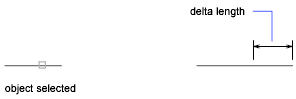
Delta
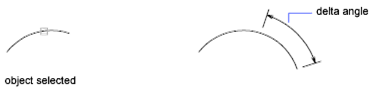
Changes the length of an object by a specified increment, measure from the endpoint that is closest to the selection point. Delta also changes the angle of an arc by a specified increment, measured from the endpoint that is closest to the selection point. A positive value extends the object; a negative value trims it.
Delta Length
Changes the length of the object by the specified increment.
Angle
Changes the included angle of the selected arc by the specified angle.
Percent
Sets the length of an object by a specified percentage of its total length.
Total
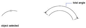
Sets the length of a selected object by specifying the total absolute length from the fixed endpoint. Total also sets the included angle of a selected arc by a specified total angle.
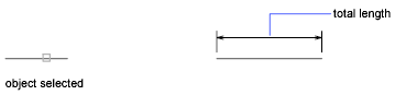
Total Length
Lengthens the object to the specified value from the endpoint that is closest to the selection point.
Angle
Sets the included angle of the selected arc.
Dynamic
Turns on Dynamic Dragging mode. You change the length of a selected object by dragging one of its endpoints. The other end remains fixed.
Powered by AutoCAD®
Related Articles
AutoCAD Keyboard Commands
Learning how to use AutoCAD keyboard commands can help you work faster and improve your efficiency. This article lists the abbreviated commands that can be used in AutoCAD (Toolbox). Toggle General Features Ctrl+G Toggle Grid Ctrl+E Cycle isometric ...3DPOLY Command
Creates a 3D polyline. A 3D polyline is a connected sequence of straight line segments created as a single object. 3D polylines can be non-coplanar; however, they cannot include arc segments. The following prompts are displayed: Start Point of ...ACTBASEPOINT Command
Inserts a base point or base point prompt in an action macro. As you record an action macro, you can use this command to insert a prompt for base point input. During playback, the macro pauses to display the prompt and does not continue until a ...PSPACE Command
In a layout, switches from model space in a layout viewport to paper space. As part of designing a layout, you can create objects in paper space. Typically, you insert a title block (see INSERT) and create layout viewports (see VPORTS), which can ...OFFSET Command
Creates concentric circles, parallel lines, and parallel curves. You can offset an object at a specified distance or through a point. After you offset objects, you can trim and extend them as an efficient method to create drawings containing many ...
Recent Articles
Microvellum Release Notes | Build 26.1.0723.641
The following release notes apply to Microvellum build 26.1.0723.641. Function UI Update The Function Arguments interface has received a major visual overhaul to improve the usability, clarity, and visibility of several elements. Input fields are now ...Microvellum Release Notes | Build 26.1.0702.641
Dark Mode Fig. 1: The MV Palette in Dark Mode. To enhance the user experience when working within Microvellum, a new Dark Mode setting has been added to the software. Enabling this will apply a dark theme to most interfaces, allowing for a greater ...Microvellum Foundation Library Release Notes | Build 26.0630
Additions: Added new Fixture product Die Wall Advanced. This product takes the legacy Die Wall products to a new level. More features and advanced parametric abilities: Up to five individual unique subassembly segments, widths controlled via ...Microvellum Foundation Library Release Notes | Build 26.0527
The following release notes apply to the Microvellum Foundation Library build 26.0527. Additions Added new features for the Wood Drawer Box to have reduced sides, sub front, or back. Added 3 new global and subassembly prompts: “Wood Drawer Side ...Microvellum Release Notes | Build 26.1.0529.641
The following release notes apply to Microvellum build 26.1.0529.641. BSB Docking Size Fix An issue was reported to be occurring in Microvellum BSB 2026: when adjusting the size of a docked Microvellum palette, users found that the palette would ...