Lineweights Plot Thicker or Lighter than Expected in AutoCAD
Issue:
When plotting to PDF, printing to a physical printer, or publishing from AutoCAD, object lineweights display thicker, thinner, darker, or lighter than displayed in the drawing.
Causes:
There are several causes for this behavior, including:
- Plot lineweights is enabled.
- Scale lineweights is enabled.
- Lineweights in the drawing are set to a thick width.
- A lineweight override is set for specific objects.
- Drawing is set to plot by color.
- Quality of the PDF being plotted.
- Lineweights or transparency settings in the plot style table (CTB or STB).
- The default setting for lines is not set to 0.
Solution:
Try one or more of the following to resolve this issue:
Lineweight display looks different in AutoCAD from the printout or plot
This might be due to the lineweight display being deactivated:
- Type LWDISPLAY in the AutoCAD command line to toggle the lineweight display.
- Type ON to switch the variable on.
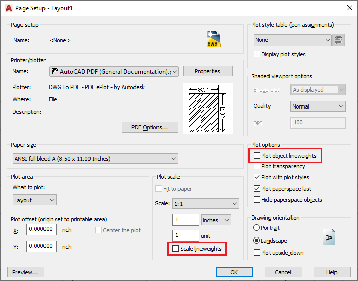
Turn off lineweight options in plot or page setup
In the Plot or Page Setup dialogue window, turn off the following two settings:
- Plot object lineweights.
- Scale lineweights.
On Windows:
On macOS:
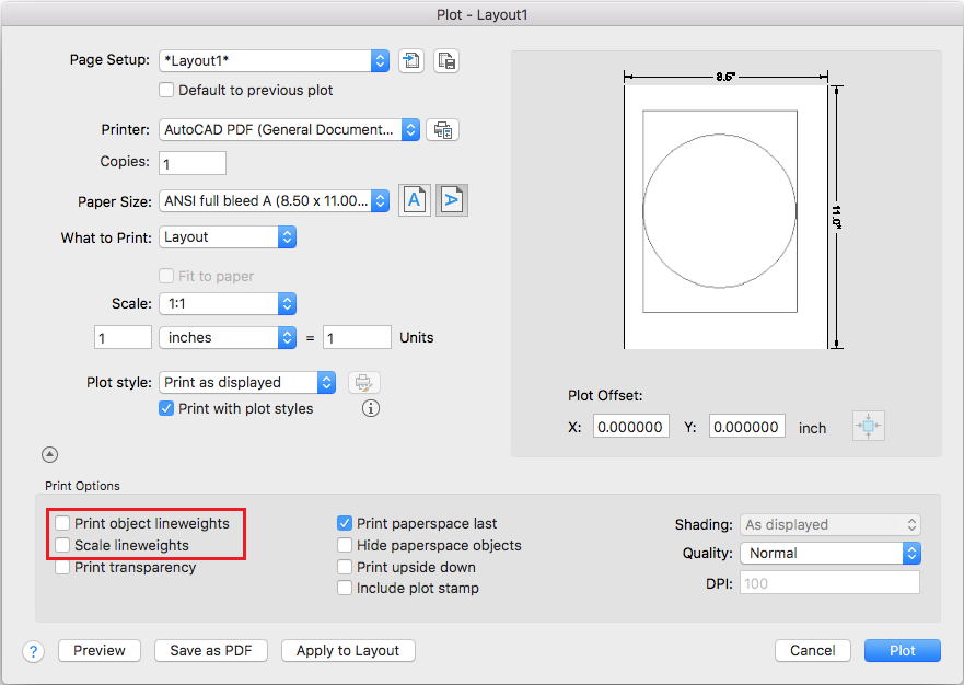

It's a good idea to save the page setup when you are done and apply it to all the layouts in your template so when you publish your jobs the settings will be applied automatically on all pages.
Change lineweight to the desired thickness
- On the ribbon in AutoCAD, click the Home tab > Layers Panel > Layer Properties.
- In the Layer Properties Manager, under the Lineweight column, click the lineweight to change.
- In the Lineweight dialog window, choose the lineweight to use as the default for objects on that layer.
Set the object lineweight to be controlled by the layer
- Select the objects.
- Type PROPERTIES in the command line and press Enter.
- Under the Lineweight drop-down, select ByLayer.

Note: Blocks and Xrefs will need to be opened to change the lineweight for objects within them.
Check that the layer is using the correct lineweight
- Select the objects.
- Type PROPERTIES in the command line and press Enter.
- Under the Lineweight drop-down, verify that it is set to ByLayer.
- Enter LAYER .
- In the Layer Manager, go to the relevant layer.
- Set the desired lineweight there.
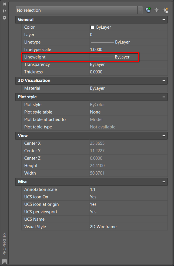
Set the drawing so that object lineweight is controlled by the layer
- With no objects selected, type PROPERTIES and press Enter.
- Under the Lineweight drop-down, select ByLayer.
Change the lineweight for dimension lines
- Check which dimstyle is used for the dimension which has thick lines.
- Enter DIMSTYLE in the AutoCAD command line.
- Select the corresponding dimstyle.
- Change the lineweight to a thinner style.
- Press OK.
- Some dimensions might need to be created new.
Select a PDF plotter or settings with higher plot quality
Plot using the AutoCAD PDF (High Quality) plotter or adjust the setting of the selected driver for the highest quality plot.
Lineweights or transparency in the plot style table
Set the plotted lineweight and transparency in the desired plot style table (see To Set the Plotted Lineweights ).
- Type PLOT in the command line.
- Press the button next to the Plot Style Table to edit the CTB file. This example edits the Grayscale.ctb file.
- In the Form View Tab, edit the Lineweight for color 1 as desired. For example: set it to 0.7000 mm.
- Press the Save As option to make a new Plot Style Table.
- Name the new Plot Style Table file. For example, Grayscale_edited.ctb .
- Press Save and Close.
- Press ESC to exit the plot layout window.
- Type PLOT again and change the Plot Style Table to Grayscale_edited.ctb
- Click OK.

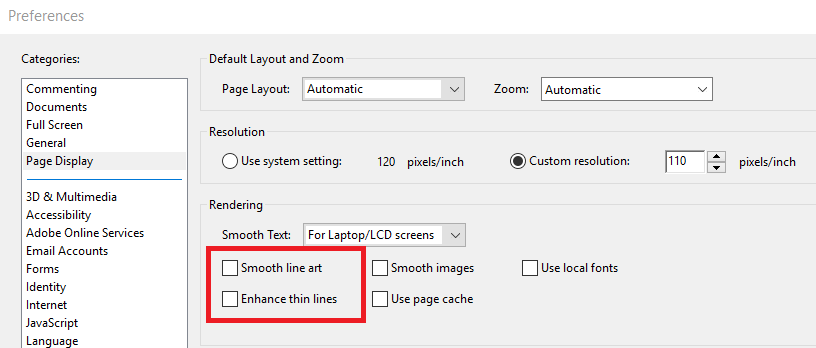
Change line thickness settings in the PDF viewer
Select a PDF plotter or settings with higher plot quality.
Try deactivating or activating both these settings:
- Smooth line art.
- Enhance thin lines.
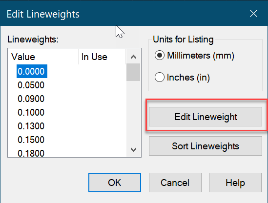
Check the settings of the Default lineweight value for Polylines
- Type LWDEFAULT to command line and Enter.
- Change the value to 0.
Related Articles
AutoCAD Keyboard Commands
Learning how to use AutoCAD keyboard commands can help you work faster and improve your efficiency. This article lists the abbreviated commands that can be used in AutoCAD (Toolbox). Toggle General Features Ctrl+G Toggle Grid Ctrl+E Cycle isometric ...Overview: Sheet Set Manager - AutoCAD
The Sheet List tab displays an ordered list of sheets. You can organize these sheets under headings, called subsets, that you create. List of Options This tab has the following buttons: Publish to DWF Publishes selected sheets or a sheet set to a ...Microvellum Commands vs AutoCAD Commands
Microvellum AC, as a software based in AutoCAD, possesses the full range of AutoCAD commands for use in accessing AutoCAD functions, such as drawing shapes, opening menus, altering the dimensions of polylines, etc. However, it should be noted that ...About Sheet Sets in AutoCAD
You can manage multiple drawings as sheet sets with the Sheet Set Manager: A sheet is a selected layout from a drawing file. You can import a layout from any drawing into a sheet set as a numbered sheet. A sheet set is an organized and named ...To Work with Comparing XREFs in AutoCAD
Use various commands and display options in the Xref Compare toolbar to review the differences between the attached xref and the referenced drawing file. Compare the Xref Changes Click View tab > Palettes panel > External References Palette. Find ...
Recent Articles
Microvellum Release Notes | Build 26.1.0723.641
The following release notes apply to Microvellum build 26.1.0723.641. Function UI Update The Function Arguments interface has received a major visual overhaul to improve the usability, clarity, and visibility of several elements. Input fields are now ...Microvellum Release Notes | Build 26.1.0702.641
Dark Mode Fig. 1: The MV Palette in Dark Mode. To enhance the user experience when working within Microvellum, a new Dark Mode setting has been added to the software. Enabling this will apply a dark theme to most interfaces, allowing for a greater ...Microvellum Foundation Library Release Notes | Build 26.0630
Additions: Added new Fixture product Die Wall Advanced. This product takes the legacy Die Wall products to a new level. More features and advanced parametric abilities: Up to five individual unique subassembly segments, widths controlled via ...Microvellum Foundation Library Release Notes | Build 26.0527
The following release notes apply to the Microvellum Foundation Library build 26.0527. Additions Added new features for the Wood Drawer Box to have reduced sides, sub front, or back. Added 3 new global and subassembly prompts: “Wood Drawer Side ...Microvellum Release Notes | Build 26.1.0529.641
The following release notes apply to Microvellum build 26.1.0529.641. BSB Docking Size Fix An issue was reported to be occurring in Microvellum BSB 2026: when adjusting the size of a docked Microvellum palette, users found that the palette would ...