LOFT Command
Creates a 3D solid or surface in the space between several cross sections.
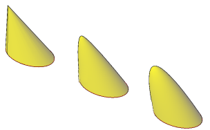
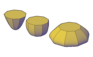
Creates a 3D solid or surface by specifying a series of cross sections. The cross sections define the shape of the resulting solid or surface. You must specify at least two cross sections.
Loft cross sections can be open or closed, planar or non-planar, and can also be edge sub-objects. Open cross sections create surfaces and closed cross sections create solids or surfaces, depending on the specified mode.
When creating surfaces, use SURFACEMODELINGMODE to control whether the surface is a NURBS surface or a procedural surface. Use SURFACEASSOCIATIVITY to control whether procedural surfaces are associative.
You can use the following objects and sub-objects with LOFT:
|
Objects That Can Be Used as Cross Sections |
Objects That Can Be Used as a Loft Path |
Objects That Can Be Used as Guides |
|
2D Polyline |
Spline |
2D Spline |
|
2D Solid |
|
|
|
2D Spline |
Helix |
3D Spline |
|
Arc |
Arc |
Arc |
|
Circle |
Circle |
2D Polyline

2D polylines can be used as guides if they contain only 1 segment.
|
|
Edge Sub-Objects |
Edge Sub-Objects |
Edge Sub-Objects |
|
Ellipse |
Ellipse |
3D Polyline |
|
Elliptical Arc |
Elliptical Arc |
Elliptical Arc |
|
Helix |
2D Polyline |
|
|
Line |
Line |
Line |
|
Planar or Non-Planar Face of Solid |
|
|
|
Planar or Non-Planar Surface |
|
|
|
Points (First and Last Cross Section Only) |
3D Polyline |
|
|
Region |
|
|
|
Trace |
|
|
The following prompts are displayed:
Cross Sections in Lofting Order
Specifies open or closed curves in the order in which the surface or solid will pass through them.
Point
Specifies first or last point of the lofting operation. If you start with the Point option, you must next select a closed curve.
Join Multiple Edges
Handles multiple, end-to-end edges as one cross section.
Mode
Controls whether the lofted object is a solid or a surface.
Continuity
This option only displays if the LOFTNORMALS system variable is set to 1 (smooth fit). Specifies whether the continuity is G0, G1, or G2 where the surfaces meet.
Bulge Magnitude
This option only displays if the LOFTNORMALS system variable is set to 1 (smooth fit). Specifies a bulge magnitude value for objects that have a continuity of G1 or G2.
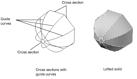
Guides
Specifies guide curves that control the shape of the lofted solid or surface. You can use guide curves to control how points are matched up on corresponding cross sections to prevent undesired results, such as wrinkles in the resulting solid or surface.
- Intersects each cross section
- Starts on the first cross section
- Ends on the last cross section
Select any number of guide curves for the lofted surface or solid and press Enter.
Path
Specifies a single path for the lofted solid or surface.
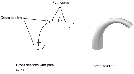
The path curve must intersect all planes of the cross sections.
Cross Sections Only
Creates lofted objects without using guides or paths.
Settings
Displays the Loft Settings dialog box.
Powered by AutoCAD®
Related Articles
AutoCAD Keyboard Commands
Learning how to use AutoCAD keyboard commands can help you work faster and improve your efficiency. This article lists the abbreviated commands that can be used in AutoCAD (Toolbox). Toggle General Features Ctrl+G Toggle Grid Ctrl+E Cycle isometric ...3DPOLY Command
Creates a 3D polyline. A 3D polyline is a connected sequence of straight line segments created as a single object. 3D polylines can be non-coplanar; however, they cannot include arc segments. The following prompts are displayed: Start Point of ...ACTBASEPOINT Command
Inserts a base point or base point prompt in an action macro. As you record an action macro, you can use this command to insert a prompt for base point input. During playback, the macro pauses to display the prompt and does not continue until a ...PSPACE Command
In a layout, switches from model space in a layout viewport to paper space. As part of designing a layout, you can create objects in paper space. Typically, you insert a title block (see INSERT) and create layout viewports (see VPORTS), which can ...OFFSET Command
Creates concentric circles, parallel lines, and parallel curves. You can offset an object at a specified distance or through a point. After you offset objects, you can trim and extend them as an efficient method to create drawings containing many ...
Recent Articles
Microvellum Release Notes | Build 26.1.0723.641
The following release notes apply to Microvellum build 26.1.0723.641. Function UI Update The Function Arguments interface has received a major visual overhaul to improve the usability, clarity, and visibility of several elements. Input fields are now ...Microvellum Release Notes | Build 26.1.0702.641
Dark Mode Fig. 1: The MV Palette in Dark Mode. To enhance the user experience when working within Microvellum, a new Dark Mode setting has been added to the software. Enabling this will apply a dark theme to most interfaces, allowing for a greater ...Microvellum Foundation Library Release Notes | Build 26.0630
Additions: Added new Fixture product Die Wall Advanced. This product takes the legacy Die Wall products to a new level. More features and advanced parametric abilities: Up to five individual unique subassembly segments, widths controlled via ...Microvellum Foundation Library Release Notes | Build 26.0527
The following release notes apply to the Microvellum Foundation Library build 26.0527. Additions Added new features for the Wood Drawer Box to have reduced sides, sub front, or back. Added 3 new global and subassembly prompts: “Wood Drawer Side ...Microvellum Release Notes | Build 26.1.0529.641
The following release notes apply to Microvellum build 26.1.0529.641. BSB Docking Size Fix An issue was reported to be occurring in Microvellum BSB 2026: when adjusting the size of a docked Microvellum palette, users found that the palette would ...