REVOLVE Command
Open profiles create surfaces and closed profiles can create either a solid or a surface. The Mode option controls whether a solid or a surface is created. When creating a surface, SURFACEMODELINGMODE system variable controls if a procedural or NURBS surface is created.
- Open or closed
- Planar or non-planar
- Solid and surface edges
- A single object (to extrude multiple lines, convert them to a single object with the JOIN command)
- A single region (to extrude multiple regions, first convert them to a single object with the UNION command)
To automatically delete the profile, use the DELOBJ system variable. If associativity is on, the DELOBJ system variable is ignored and the originating geometry is not deleted.
|
Surfaces |
Elliptical Arcs |
2D Solids |
|
Solids |
2D and 3D Splines |
Traces |
|
Arcs |
2D and 3D Polylines |
Ellipses |
|
Circles |
Regions |
|
 Select face and edge sub-objects by pressing Ctrl while you select them.
 You cannot revolve objects contained within a block or objects that will self-intersect. REVOLVE ignores the width of a polyline and revolves from the center of the path of the polyline.
The right-hand rule determines the positive direction of rotation.
Objects to Revolve
Specifies the objects to be revolved about an axis.
Mode
Controls whether the revolve action creates a solid or a surface. Surfaces are extended as either NURBS surfaces or procedural surfaces, depending on the SURFACEMODELINGMODE system variable.
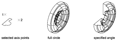
Axis Start Point
Specifies the first point of the axis of revolution. The positive axis direction is from the first to the second point.
Axis Endpoint
Sets the endpoint for the axis revolution.
Start Angle
Specifies an offset for the revolution from the plane of the object being revolved.
Drag your cursor to specify and preview the start angle of the object.
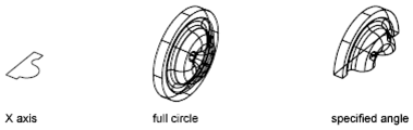
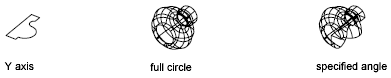
Angle of Revolution
Specifies how far the selected object revolves about the axis.
A positive angle revolves the objects in a counterclockwise direction. A negative angle revolves the objects in a clockwise direction. You can also drag the cursor to specify and preview the angle of revolution.
Object
Specifies an existing object to be used as an axis. The positive axis direction is from the closest to the farthest endpoint of this object.
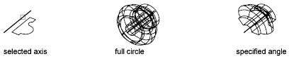
You can use lines, linear polyline segments, and linear edges of solids or surfaces as an axis.
Select an edge sub-object by pressing Ctrl while you select an edge.
X (Axis)
Sets the positive X axis of the current UCS as the positive axis direction.
Y (Axis)
Sets the positive Y axis of the current UCS as the positive axis direction.
Z (Axis)
Sets the positive Z axis of the current UCS as the positive axis direction.
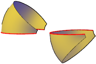
Reverse
Changes the direction of the revolve; similar to entering a - (minus) angle value. The revolved object on the right shows a spline revolved at the same angle as the object on the left, but using the reverse option.
Expression
Enter a formula or equation to specify the revolve angle.
Powered by AutoCAD®
Related Articles
REVSURF Command
Creates a mesh by revolving a profile about an axis. Select a line, arc, circle, or 2D or 3D polyline to sweep in a circular path around a selected axis. The MESHTYPE system variable sets which type of mesh is created. Mesh objects are created by ...AutoCAD Keyboard Commands
Learning how to use AutoCAD keyboard commands can help you work faster and improve your efficiency. This article lists the abbreviated commands that can be used in AutoCAD (Toolbox). Toggle General Features Ctrl+G Toggle Grid Ctrl+E Cycle isometric ...3DPOLY Command
Creates a 3D polyline. A 3D polyline is a connected sequence of straight line segments created as a single object. 3D polylines can be non-coplanar; however, they cannot include arc segments. The following prompts are displayed: Start Point of ...ACTBASEPOINT Command
Inserts a base point or base point prompt in an action macro. As you record an action macro, you can use this command to insert a prompt for base point input. During playback, the macro pauses to display the prompt and does not continue until a ...PSPACE Command
In a layout, switches from model space in a layout viewport to paper space. As part of designing a layout, you can create objects in paper space. Typically, you insert a title block (see INSERT) and create layout viewports (see VPORTS), which can ...
Recent Articles
Microvellum Release Notes | Build 26.1.0723.641
The following release notes apply to Microvellum build 26.1.0723.641. Function UI Update The Function Arguments interface has received a major visual overhaul to improve the usability, clarity, and visibility of several elements. Input fields are now ...Microvellum Release Notes | Build 26.1.0702.641
Dark Mode Fig. 1: The MV Palette in Dark Mode. To enhance the user experience when working within Microvellum, a new Dark Mode setting has been added to the software. Enabling this will apply a dark theme to most interfaces, allowing for a greater ...Microvellum Foundation Library Release Notes | Build 26.0630
Additions: Added new Fixture product Die Wall Advanced. This product takes the legacy Die Wall products to a new level. More features and advanced parametric abilities: Up to five individual unique subassembly segments, widths controlled via ...Microvellum Foundation Library Release Notes | Build 26.0527
The following release notes apply to the Microvellum Foundation Library build 26.0527. Additions Added new features for the Wood Drawer Box to have reduced sides, sub front, or back. Added 3 new global and subassembly prompts: “Wood Drawer Side ...Microvellum Release Notes | Build 26.1.0529.641
The following release notes apply to Microvellum build 26.1.0529.641. BSB Docking Size Fix An issue was reported to be occurring in Microvellum BSB 2026: when adjusting the size of a docked Microvellum palette, users found that the palette would ...