Overview: Scrap Management
The operating procedures of some companies sometimes contain a gray area with regard to what to do with wood waste, remnants, offcuts, offal, or "scrap" as we call it. There are varieties of ideas of what to do with the stuff. Some grind it to sawdust and send it off to the dust bin, while others add it to their material inventory and use it in subsequent projects to maximize profits.
Microvellum contains functionality to generate scrap sheets when using the nesting optimizer or the sawing optimizer, as well as the ability to process the waste pieces that remain after the scrap sheets have been identified. A part label is printed along with the other optimized part labels, identifying the scrap piece, as it is stored for future use.
It also supports the management of the scrap inventory with a selection of tools to match the specific tasks you need to perform to manage it.
The description and procedure below is an overview of the functionality. This assumes you are already familiar with Toolbox. If not, or if unclear about the details, you will find links to tutorials giving the exact steps of various parts of this procedure at the end of this article. Most, but not all of the description below, applies to both Library materials and Project level materials, in both Toolbox and ERP. See the notes attached to the sections that do not apply to both types of materials.
General Procedure Summary
- Configure Scrap Storage Locations
- Add Scrap Materials or Scrap Sheet Sizes to Inventory
- Configure Processing Station Scrap Properties
- Create Scrap Material Sheets
- Commit Scrap Sheets to Inventory
- Use Scrap Sheets from Inventory
- Subtract Scrap Sheets from Inventory
1 - Configure Scrap Storage Locations
The first step to start using the scrap functionality is to decide on the locations for storing your scrap. There are five default storage locations available, or you may configure your new custom locations, as shown below.
You may also manage the storage locations and other scrap options from within the Processing Center, using the Scrap Options menu.
Once your locations have been set up, they are then available for specifying a Location property in each scrap material accessed from the Manage Scrap Inventory command.
2 - Add Scrap Materials or Scrap Sheet Sizes to Inventory
The second step is to add any existing scrap to the inventory that you have lying around your facility. This is done by adding new material in your spec groups as needed, or if the material already exists, by adding a new sheet to that material and adjusting its size. You may add materials to your scrap sheet inventory from two different locations, as explained below.
- Manage Inventory
- Edit Selected Material
Manage Inventory
The first way to add materials to your scrap sheet inventory is from the Manage Inventory button in the Options boxes (Toolbox Setup > Options > Processing > Manage Inventory > Add Scrap From Material…). This displays a list of your factory materials, from which you double click to select one material.
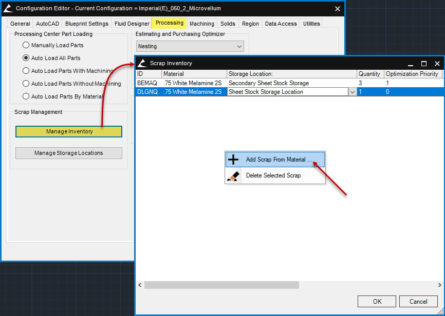
Fig. 04 – Add Scrap from Material Access.
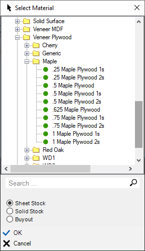
Fig. 05 - Select Material for New Scrap from Material Box (Manage Inventory).
When entered from the Manage Inventory command (Toolbox Setup > Options > Processing > Manage Inventory > Add Scrap From Material…), the scrap is entered in the inventory as an additional sheet of the selected material with a different size, inheriting all the parent material properties. This means that the program treats scrap material sheets the same as full sheets of non-scrap materials. This includes the material Optimization Priorities value and material size values. This supports the intuitive entry of scrap materials, as well as increased program speed and stability when processing.
 When you add or delete the scrap using the Manage Inventory button, it is also added or deleted from the material file accessed by Edit Selected Material.
Edit Selected Material
You may also add a new sheet size to an existing material from within the material file (Library Specification Groups > Open Material File > Edit Selected Material). Use the command "Edit Selected Material" from the right-click context menu in the material Sheet Stock Library of a spec group.
This applies to only materials from the Library Specification Groups, not those from the Project Specification Groups.
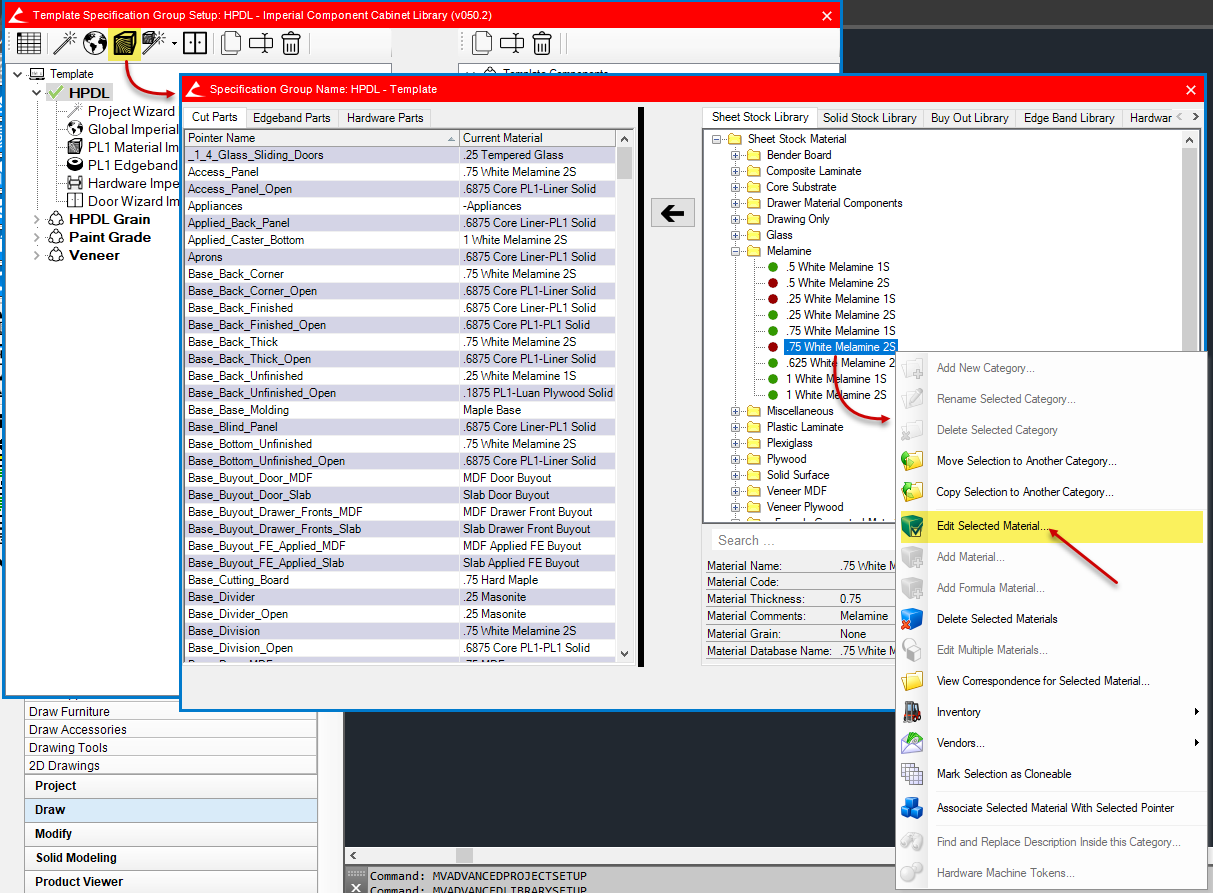
Fig. 06 – Add Sheet Size from Edit Selected Material.
When adding it here, but sure to check the checkbox for IsScrap.
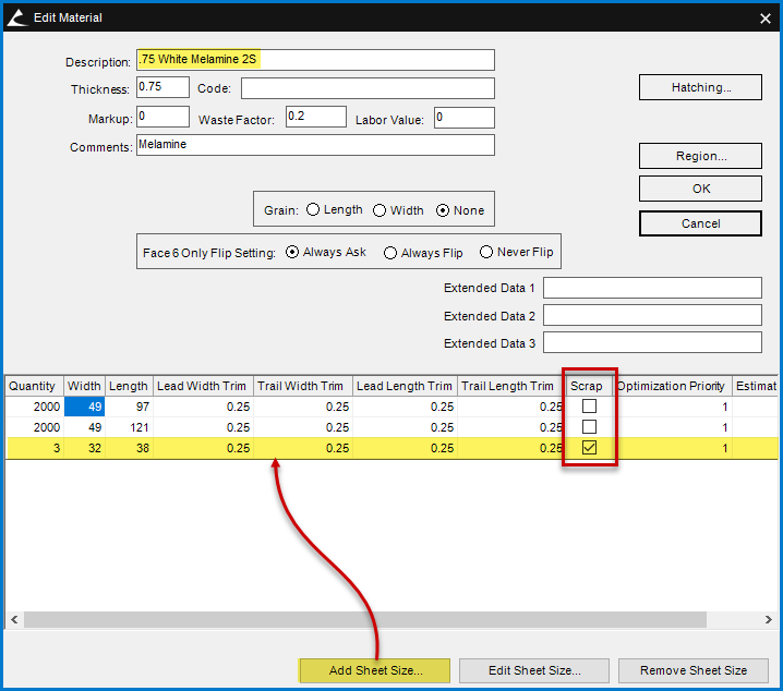
Fig. 07 – Added Scrap Sheet Size for a Material.
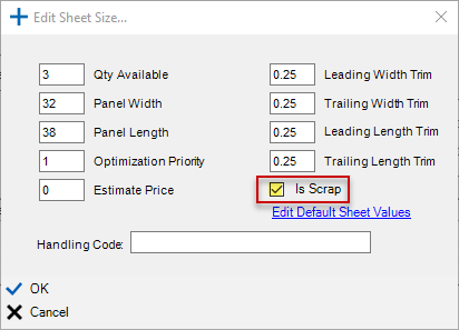
Fig. 08 – Edit Sheet Size Properties.
Since managing the scrap material inventory is possible from two locations, it is important to remember that the two locations are linked. Making a change in one interface will update the other, provided that both properties exist in both interfaces.
Once the scrap has been entered using one interface or the other, you can then modify the scrap material as you would any other material. This includes the Code, Estimate Price, Markup, Comments, Quantity, Optimization Priority, etc.
Also, be sure to assign a scrap location as previously configured to this new inventory material and any other materials in the Scrap Inventory for which it has not yet been assigned. Set the remaining material properties as needed by scrolling to the right in the dialog box. (See tutorials for details.)
You will also notice that among the properties (columns) in this dialog box is one for a scrap ID. This is a unique alpha-numeric identification of that particular scrap sheet that is also used on the optimization report and part label.
3 - Configure Processing Station Scrap Properties
The third step is to configure each of your processing stations to include the scrap properties needed for that station. There are two ways to access these properties. One is from Processing Stations Setup, and the other is editing the processing station from within the Processing Center. Both result in the same dialog box.
As shown in the figure below, you may highlight the processing station and click the Edit button. Alternatively, you simply double click on the processing station in the list.
Within this dialog, you have the option of whether or not you Save or create scrap materials when optimizing, and whether you Use scrap from the inventory when optimizing. Check the appropriate checkbox.
See Scrap Management (Reference) in the Microvellum Help Center for a concise reference giving the name and a brief description of each property in the Scrap Settings box. This article is an overview only.
Save Scrap Meeting the Following Requirements
You may control your scrap yield by indicating how much of your waste offcut material is utilized to create Microvellum scrap materials.
Use Scrap from Inventory
For the first scrap yield setting, you specify the minimum area for a scrap sheet, regardless of the precise width and length dimensions. If you apply a value of 720 square inches, the scrap sheet could either be 24" x 30", or it could be 16" x 45". They both equal the 720 value entered.
For the second scrap yield setting, you specify a minimum dimension for the scrap sheets, which can be either the width or length of the sheet. If you apply a value of 24 inches here, no part will be under 24 inches, in either width or length of the sheet, or both as explained below.
The third scrap yield setting applies to the Minimum Scrap Dimension setting. You select either "Length OR Width must exceed Min Dimension," or "Length AND Width must exceed Min Dimension." If an unused section of the original material sheet is to qualify as a scrap sheet, either one dimension of the potential scrap sheet, or the other dimension must be greater than the minimum dimension value specified in the Minimum Scrap Dimension box ("OR" option). Alternatively, both of the sheet dimensions must be greater than the minimum dimension value ("AND" option).
Use the option for Automatically Consume Scrap Inventory to eliminate the need to manually move scrap from the scrap created when processing a batch to the permanent scrap inventory. When this box is checked ON the program commits or saves scrap automatically when the work order is processed without any further intervention.
You specify if you want to override the scrap trim values set in the material inventory with the checkbox for Override Scrap Inventory Trim. This overrides the material inventory trim values with those specified here for a specific CNC machine or processing station. This would be used to minimize material loss from two separate rounds of trim cuts. The first trim cut is taken when the scrap sheet is cut from the original sheet, and the second trim cut is taken when the part is cut from the scrap sheet. This trim cut override allows you to quickly and easily reduce or remove the redundant trim cuts when the scrap sheet is cut from the original sheet without having to edit the four trims for each scrap piece, one at a time. To maximize material yield, these override trim values are set to zero by default, but that value may be modified as needed.
Offal Destruction
The Scrap tab for nesting type processing stations contains an additional section and related properties when compared to the Scrap tab for sawing type stations. These additional settings all refer to what we call offal or scrap destruction. Offal or scrap both refer to the material that remains after cabinet parts, or scrap sheets are cut out. This is material that is normally thrown away, but the disposal of it can pose a problem.
Using the option Destroy Offal in the nesting type processing stations, you set parameters for the destruction of this left-over material. You may leave it in pieces in sizes that you specify, or you may turn it to sawdust if you prefer. The tradeoff is machining time and tool wear. The smaller the pieces you leave remaining, the longer the nest takes to complete the machining operation for some shops that is an acceptable exchange.
Set Maximum Dimension 1 and 2 to the values that provide the balance of machining time and offal size you need.
Figure 13 shows the effect of a Maximum Dimension 1 = 6 and Maximum Dimension 2 = 3.
Figure 14 shows the effect of a Maximum Dimension 1 = 1 and Maximum Dimension 2 = 1 on the same nest.
Set Sheet Edge Trim to either a positive or negative value that indicates the distance from the sheet border that parallel offal destruction machining paths are located. A positive value places the offal destruction machining inside the sheet border, while a negative value places it outside the sheet border.
See figure 13 below for an example of zero (0) Sheet Edge Trim.
See figure 14 below for an example of a negative half-inch (0.5") Sheet Edge Trim.
Offal Destruction Type and True Shape Parts
Use the Type option "Create Pattern for Entire Sheet" if you are doing true shape nesting. It delivers improved detection of offal in areas separated from each other by arced or other non-rectangular parts.
Offal Destruction Sequence and Order of Machining
We understand that various users have different preferences for the order of machining the offal destruction relative to the nested parts. Therefore, we have included two options in the Sequence section of the scrap properties – Destroy before routing borders, and Destroy after routing borders. Select the option that best addresses your machining needs.
Process Work Order with Stations Set Up to Produce Scrap
Once your scrap locations have been set up, your existing scrap added to your material inventory, and the scrap settings set up for each processing station that will be processing scrap, you are ready to process a work order with a processing station set to either a Type of Nesting Optimizer or Microvellum Sawing Optimizer.
Remember that when processing and optimizing using a station of one of those two types, you must check the checkbox for the functionality you want to activate. This is done by editing the processing station, clicking on the Scrap tab, and checking one or more of the checkboxes shown below.
4 - Create Scrap Material Sheets
Once this initial setup has been completed, you are ready to begin creating and saving the scrap pieces that match the parameters that you already setup to be applied to individual material sheets. You do this by processing the work order. This results in 'potential' scrap but does not automatically save it to your material inventory. There is another step to save it to the inventory database. This is necessary because there is the possibility that you may discover something about that work order that needs correction and re-processing to another batch. If the program automatically added the scrap to the database, the multiple batches would result in bloated inventory values.
But before you save the scrap to the inventory, make sure that the 'nested patterns' or 'sawing patterns' are correct by viewing either the Nesting Optimization Report or the Sawing Optimization Report, the nest, or sawing layout patterns, or the nest composite drawing. The nesting results are shown below, but the sawing results are very similar, except that there is no composite drawing for the sawing results.
Print the part labels and place them on the parts as the machining process is completed. Each scrap sheet that was produced will be displayed as a part in the 'nested pattern' or 'sawing pattern' and will generate a label.
Use this scrap label later as scrap is consumed and used as a material sheet, to identify it.
5 - Commit Scrap Sheets to Inventory
When you have verified that the work order is in its final form and the scrap produced is correct, it's the time to commit or add that scrap to the material inventory. That is accomplished with the Processing Center open, from Scrap Options, "Commit Scrap To Inventory."
The list of batches under the heading "Work Order Batches" contains only those batches that contain uncommitted scrap sheets. The Commit Scrap To Inventory dialog box is updated each time it is opened. If it does not display the data, you think it should refresh the display by reopening it.
To add a saved scrap sheet, select the Work Order Batch, select the scrap material under the heading Scrap Saved From Batch, select a Material Storage Location from the dropdown list, and then click the arrow button. Repeat this for all saved scraps being saved to a storage location.
The screenshot below shows the material for ".75 White Melamine 2S" before and after three scrap sheets were added manually to the inventory, and a single scrap sheet has been committed from a scrap part generated when processing.
6 - Use Scrap Sheets from Inventory
Once the scrap sheets have been committed to the inventory, you are ready to begin saving money by using those sheets in other projects.
Make sure the checkbox "Use Scrap From Inventory" is checked as described in section 3 above. Create a new work order, or open an existing work order and process using a nesting or sawing type station with scrap enabled as also described in section 3.
When processing, regardless of whether you Save or Use scrap, the software calculates the priority of each sheet based on its material level property "Optimization Priority," and the sheet size (area). These two values are sorted in ascending order, and the sheets with the lowest values are filled with parts first in the optimization process. In simple terms, the smallest sheets are filled first when possible. If the smallest scrap sheet of a particular material is too small to fit any part being optimized, it will be skipped, and the next largest sheet will be considered in the process.
If you have the checkbox checked for "Use Scrap From Inventory," the scrap sheets that have already been committed to inventory are included in this process, the same as the non-scrap materials.
The program processes parts to scrap sheets before it processes them to full sheets of material. As the program is processing parts, it keeps track of how many scrap sheets are available. When the available scrap sheets have exhausted, it will begin to process to full material sheets.
Unless you have set the option for automatic scrap consumption as discussed in section 7 below, the inventory for the scrap sheets will not be adjusted until you manually move them to the box Scrap Consumed From Inventory (see Figure 28).
7 - Subtract Scrap Sheets from Inventory
When you have verified that the work order using previously saved scrap sheets is acceptable and the scrap utilization is correct, it's the time to subtract that scrap from the material inventory.
There are two ways to accomplish this within Microvellum. The first requires human intervention and is similar to the process for committing scrap. The benefit of this method of subtracting scrap consumed is that you may review and finalize the scrap utilization before the change is committed and the inventory adjusted. It provides greater flexibility. The second requires no human intervention and is performed automatically by the software. The benefit of this method is that it is completed more quickly, with no additional work by the user. It provides greater speed.
Manually Subtract Scrap Sheets from Inventory
That is accomplished with the Processing Center open, from Scrap Options, "Commit Scrap To Inventory." This time the box for "Scrap Used By Batch" will be populated with the scrap materials used in the optimization.
To subtract a saved scrap sheet, select the Work Order Batch, select the scrap material under the heading "Scrap Used By Batch," and click the arrow button. Repeat this for all saved scrap being subtracted or consumed from a storage location.
Automatically Consume Scrap Sheets from Inventory
You may also set a processing station option to Automatically Consume Scrap Inventory. This option subtracts a scrap sheet from the inventory without any further intervention on your part. This option is appealing if you seldom review and re-process a work order based on the scrap optimization results. Select this option if you always commit the first scrap optimization offered by Microvellum.
The screenshot below continues from figure 29 to show the Scrap Inventory after a scrap sheet has been automatically consumed. No further involvement beyond processing the work order was required.
See Scrap Management (Reference) in the Microvellum Knowledge Base for a reference of the scrap management properties.
Related Articles
Reference: Scrap Management
Access to Scrap Inventory and Scrap Storage Locations (Bins) Scrap Inventory can be accessed from the Options window and from the Processing Center. From Options: Select the “Processing” tab. Within the “Scrap Management” area select “Manage ...Adding a Project Name to a Part Label Scrap Name Field
You may want to add a project name to a part label that contains fields displaying the scrap material names. If this is done using a current default Microvellum part label as a template, the process is quite easy, as shown by the screencast attached. ...Overview: 15.6 Processing Center
The Microvellum Processing Center is an indispensable tool in the production of manufacturing data for your company. Countless users depend on it every day to edit processing stations, create g-code, print reports, and labels, work with the nest ...Overview: Configuring Biesse Winstore System
This article presents a brief overview of the Microvellum connection to the Biesse Winstore material handling system. First, it is important to understand that the communication with the Biesse Winstore is one-way, meaning that Microvellum transmits ...Using Business Objects in Reports (Overview)
The term "Business Object" is used in Microvellum to describe an object or entity that encapsulates or contains data. The Microvellum Business Objects are used in reports. They are set up when configuring the report dataset and contain either the ...
Recent Articles
Microvellum Release Notes | Build 26.1.0723.641
The following release notes apply to Microvellum build 26.1.0723.641. Function UI Update The Function Arguments interface has received a major visual overhaul to improve the usability, clarity, and visibility of several elements. Input fields are now ...Microvellum Release Notes | Build 26.1.0702.641
Dark Mode Fig. 1: The MV Palette in Dark Mode. To enhance the user experience when working within Microvellum, a new Dark Mode setting has been added to the software. Enabling this will apply a dark theme to most interfaces, allowing for a greater ...Microvellum Foundation Library Release Notes | Build 26.0630
Additions: Added new Fixture product Die Wall Advanced. This product takes the legacy Die Wall products to a new level. More features and advanced parametric abilities: Up to five individual unique subassembly segments, widths controlled via ...Microvellum Foundation Library Release Notes | Build 26.0527
The following release notes apply to the Microvellum Foundation Library build 26.0527. Additions Added new features for the Wood Drawer Box to have reduced sides, sub front, or back. Added 3 new global and subassembly prompts: “Wood Drawer Side ...Microvellum Release Notes | Build 26.1.0529.641
The following release notes apply to Microvellum build 26.1.0529.641. BSB Docking Size Fix An issue was reported to be occurring in Microvellum BSB 2026: when adjusting the size of a docked Microvellum palette, users found that the palette would ...