Understanding the Blocks Palette
Blocks can be inserted into a drawing with the Blocks Palette, the Tool Palettes window, or Design Center, depending on which of these tools best suits the user's needs. This article focuses on the Blocks Palette.
To access the Blocks Palette, enter the BLOCKSPALETTE command, or select Insert at the top of the window > select Block….
Control Options
At the top of the Blocks Palette, the following display and access control options are available:
- Filter – The filter option uses wildcard characters to filter the available blocks. Valid wildcard characters are (?) for a single character and (*) for multiple characters. For example, (3??B*) displays blocks named "30xB123" and "3x8BC." The drop-down list shows previously used wildcard strings.
- Insert DWG as Block
– The Insert DWG as Block option displays a file explorer interface for selecting a drawing file to insert into the current drawing as a block.
- List Style or Icon (Display Options) – Displays several options to list or preview the available blocks.

Insertion Options
- Insertion Point – This specifies the insertion point for the Block. While checked, the insertion point is specified when inserting the Block, using either the pointing device or by entering coordinates manually. While cleared, the coordinates specified previously are used.
- Scale – Specifies the scale for the inserted Block. While checked, the scale factors in the X, Y, and Z directions must be specified. Entering a negative value for the X, Y, and Z scale factors inserts the Block as a mirror image around that axis. While cleared, previously specified scales are used.
- Uniform Scale – Specifies a single scale value for the X, Y, and Z coordinates.
- Rotation and Angle – Specifies the rotation angle for the inserted Block in the current UCS. When checked, you specify the Block's rotation angle using the pointing device or entering an angle. When cleared, the previously established angle is inserted once.
- Repeat Placement – Controls whether the block insertion automatically repeats. When checked, the user is prompted automatically for additional insertion points until Esc is pressed to cancel the command. While cleared, the Block you specified is inserted once.
- Explode – Controls whether the Block is automatically exploded into its component objects while inserted. The Block's preview at the cursor is suppressed as an indication that the Block is exploded on insertion.
While checked, the component objects in the Block are disassociated and revert to their original properties. Objects using the BYBLOCK color are white. Objects with BYBLOCK line type use CONTINUOUS line type.
Blocks Palette Tabs
- Current Drawing
- Recent
- Other Drawing
Current Drawing
The Current Drawing tab displays previews or a list of block definitions available in the current drawing.
A lightning bolt icon
in the block preview signifies that the Block is dynamic. This icon
indicates that the Block is annotative.
A block can be inserted from the Blocks Palette in one of three ways:
- Right-clicking on one of these blocks allows the selected Block to be inserted in the drawing or inserted in the drawing with the explode factor.
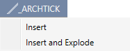
Fig. 06 – "Insert" or "Insert and Explode"
- The Blocks can also be manually dragged and dropped into the drawing.
Fig. 07 – Dragging Block to Drawing
- Left-click the Block, and select the point in the drawing for it to be placed.

Fig. 08 – Left-Click and Click the Drawing Palette where the Block is to be Placed
Hovering over a block reveals a pop-up that features information regarding the Block, including the Block Name, whether or not it's Annotative, and whether or not it's Dynamic.
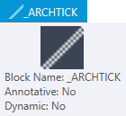
Fig. 09 – Block Information
Recent
The Recent tab displays previews or a list of block definitions recently inserted or created in the current and previous sessions. These blocks can come from the present and other recent drawings.
Right-clicking on one of these blocks allows for the following options:
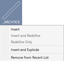
Fig. 10 – Recent Tab Context Menu
Hovering over the Block reveals the following information:
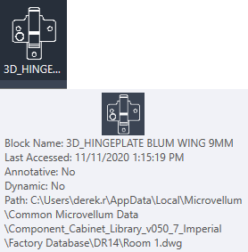
Fig. 11 – Block Information
Other Drawing
The Other Drawing tab displays a list of block definitions from another .dwg or room selected by the user.
Right-clicking on one of these blocks allows for the following options:
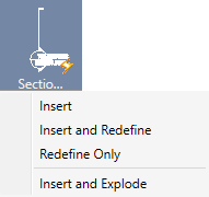
Fig. 12 – Other Drawing Tab Context Menu
Hovering over the Block reveals the following information:
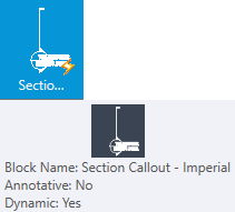
Fig. 13 – Block Information
Related Articles
About Inserting Blocks
Save time and control the drawing size by inserting references to a set of objects that have been combined to form a block. Sources of Block Definitions You can insert blocks from these sources: Blocks defined in the current drawing. Other drawing ...About Blocks
Blocks are compound objects that are commonly used for symbols, parts, detail views, and title blocks. A block is one or more objects combined to create a single object. The following are some examples of blocks inserted into drawings. Using blocks ...About Defining Blocks
You can create blocks by associating objects and giving them a name or by creating a drawing to be used as a block. Block Definitions Whenever you create a block or insert a drawing as a block, all of the block information in the block definition, ...Understanding Annotative Dimensions
Understanding Annotative Dimensions Annotative dimensions can be an enormous time saver. Annotative dimensions allow you to use a single dimension and apply one or more scales to it. The correct scale will be used when the scale is set for the ...About Modifying Block Definitions
You can modify a block definition using several methods. Modify a Block Definition There are several methods for redefining a block definition. The method you choose depends on whether you want to make changes in the current drawing only or in a ...
Recent Articles
Microvellum Release Notes | Build 26.1.0723.641
The following release notes apply to Microvellum build 26.1.0723.641. Function UI Update The Function Arguments interface has received a major visual overhaul to improve the usability, clarity, and visibility of several elements. Input fields are now ...Microvellum Release Notes | Build 26.1.0702.641
Dark Mode Fig. 1: The MV Palette in Dark Mode. To enhance the user experience when working within Microvellum, a new Dark Mode setting has been added to the software. Enabling this will apply a dark theme to most interfaces, allowing for a greater ...Microvellum Foundation Library Release Notes | Build 26.0630
Additions: Added new Fixture product Die Wall Advanced. This product takes the legacy Die Wall products to a new level. More features and advanced parametric abilities: Up to five individual unique subassembly segments, widths controlled via ...Microvellum Foundation Library Release Notes | Build 26.0527
The following release notes apply to the Microvellum Foundation Library build 26.0527. Additions Added new features for the Wood Drawer Box to have reduced sides, sub front, or back. Added 3 new global and subassembly prompts: “Wood Drawer Side ...Microvellum Release Notes | Build 26.1.0529.641
The following release notes apply to Microvellum build 26.1.0529.641. BSB Docking Size Fix An issue was reported to be occurring in Microvellum BSB 2026: when adjusting the size of a docked Microvellum palette, users found that the palette would ...