Understanding the Part Size Tab
Part Size Tab
The Part Size tab contains the values related to the size of the part and material. Review the details below for each parameter on the Part Size tab.
Part Name
The name of the part.
Quantity
The quantity of the part. Having a part with multiple quantities is usually used in conjunction with an EQ statement in the origin of the part so that that part will be evenly spaced within a given space of the product. You can find examples of EQ statements being used in Adjustable Shelf parts in the library.
Width
The width of the part.
Length
The length of the part.
Perfect Grain Info
This parameter is used to determine if a part should be perfect grained or not. The only value that is needed in this cell is 1. If a part is marked with a 1, it will be added to a perfect grain layout with other parts in the same product marked for perfect graining as well. Microvellum uses the location of the part in the product to determine how all the parts should get placed in a perfect grain pattern. This option will only work if you are using the Microvellum Nesting Optimizer, Microvellum Sawing Optimizer, or you are optimizing with ARDIS. The default Microvellum libraries setup all door and drawer front parts to be perfect grained. This option can be turned on in the global variable file. If you are optimizing with CutRite, and need to perfect grain parts, you will need to use the comments fields to pass the appropriate information to CutRite. The perfect graining globals contain more information on Perfect Graining with CutRite.
Material Name
This parameter displays the material that is currently assigned to the part. Selecting the ellipse button next to the material text box will display the Select Material window. This allows you to select a material or material pointer from the material file. Assigning a part a material that contains a minus sign in front of the material name will force the program to skip this part when processing a work order. This is common when you would like to add a part for drawing purposes only.
Comments
You can enter comments for the part in the Comments field. You can assign up to three different comments that will get transferred in the parts database table when processing a work order. A pipe symbol should separate each comment "|." Review the two examples of using comments that are hard-locked values or formula-driven values.
Hard locked Value Example
 =”Width|Height|Depth”
In this example, the word "Width" will be populated into part comment 1, "Height" will be populated into part comment 2, and "Depth" will be populated into part comment 3.
Formulas Driven Example
=Panel_Width&”|”&Panel_Length&”|Panel Width”
In this example, we are using the defined names panel_width and panel_length. The value of the parts panel width would be populated into part comment 1, not the word Panel Width. The same would be true for comment 2 for panel length, but for comment 3 since the word Panel Width is contained within quotes, the word Panel Width will be populated into comment 3.
Grain
If you are using the Microvellum Sawing Optimizer or the Microvellum Nesting Optimizer, you can overwrite the grain for individual parts using the Grain parameter. If this parameter is set to None, the part will inherit the grain set up in the material file for the part. If you select Length, the part will be placed on a sheet with the grain running along the length. If you select the Width option, the part will be placed on a sheet with the grain running along the width.
For an in-depth review of how you can use this grain parameter, and how you can populate the reports with the grain information of a part, see Overview: Part Material Graining.
Map Part
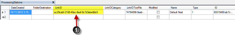
The map part field allows you to enter in, or override, the current processing stations that are assigned to this part. If a processing station link id is entered in this field, this part will automatically be assigned to that processing station within the processing center. If you do not know the processing station linkid, you will need to open the Microvellum Factory database and open the ProcessingStations table. Find the name of the processing station under the Name column and get the corresponding LinkID from the LinkID column. When adding a processing station to this field, you'll need first to specify the part grouping number, then a semi column, then the processing station LinkID. If you need multiple processing stations added to one part, each processing station should be separated by a pipe symbol. See the example below.
Formula Example
=0;7301ee57-d958-4917-be0c-3095c2e2df5e|211b2cfb-e192-4d15-a98b-8fe45c6cc57e
- Within the database, you'll need to get the processing station LinkID and add it to the map parts field.
Edgebanding Fields
Four edgebanding fields allow you to assign an edgeband material to each edge of the part. If you are unsure which edge the edgebanding will be applied to, you can right-click in the text box and select the Show This Edge menu item. The corresponding edge will be highlighted in red in the drawing.
Don't Allow Routes to be Included in Nested Border Checkbox
The Microvellum nesting optimizer contains a feature where you can include a route, such as a toe kick, as part of the nested border route. There are times where a route is too complicated and causes the nesting optimizer to produce incorrect results for the part border route. Checking this checkbox for a part will tell the optimizer not to include any routing operations assigned to this part in the part border.
Related Articles
Understanding the Hardware Tab
The Hardware Tab will display all the hardware items that are in the product or subassembly. Selecting a hardware item will display all the parameters for the hardware item. Hardware is not drawn into the drawing the same way parts are drawn. You ...Understanding the Part Properties Interface
Understanding the Part Properties Interface The Part Properties can be accessed through the Toolbox Modify tab, and then the Modify Products tab. It is also preloaded in the customizable tool strip. To view the interface, click on the Part Properties ...Introducing a New Part Properties Visualization Interface
Introducing a New Part Properties Visualization Interface We have improved the part properties visualization interface to provide more information for the selected part. We also fixed two defects in the previous build. It did not correctly display ...Understanding the Subassemblies Tab
The subassemblies tab will display the subassemblies that the product is currently referencing. A subassembly works the same way a product does. It contains its own set of parts, hardware, and prompts. A subassembly can also contain more ...Solid Model Analyzer - Solid Analyzation Tab
You will find these properties on the Solid Analyzation tab of the Microvellum Options page. Each section below contains the properties listed. Fig. 1 – Solid Analyzation Properties Material Thickness Section Fig. 2 – Material Thickness Options ...
Recent Articles
Microvellum Release Notes | Build 26.1.0723.641
The following release notes apply to Microvellum build 26.1.0723.641. Function UI Update The Function Arguments interface has received a major visual overhaul to improve the usability, clarity, and visibility of several elements. Input fields are now ...Microvellum Release Notes | Build 26.1.0702.641
Dark Mode Fig. 1: The MV Palette in Dark Mode. To enhance the user experience when working within Microvellum, a new Dark Mode setting has been added to the software. Enabling this will apply a dark theme to most interfaces, allowing for a greater ...Microvellum Foundation Library Release Notes | Build 26.0630
Additions: Added new Fixture product Die Wall Advanced. This product takes the legacy Die Wall products to a new level. More features and advanced parametric abilities: Up to five individual unique subassembly segments, widths controlled via ...Microvellum Foundation Library Release Notes | Build 26.0527
The following release notes apply to the Microvellum Foundation Library build 26.0527. Additions Added new features for the Wood Drawer Box to have reduced sides, sub front, or back. Added 3 new global and subassembly prompts: “Wood Drawer Side ...Microvellum Release Notes | Build 26.1.0529.641
The following release notes apply to Microvellum build 26.1.0529.641. BSB Docking Size Fix An issue was reported to be occurring in Microvellum BSB 2026: when adjusting the size of a docked Microvellum palette, users found that the palette would ...