Working in the Modify Products Tab
Modify Products Tab
Part Properties
See the Part Properties interface article within the Knowledge Network.
Edit Multiple Product Prompts
See How to Modify Multiple Products using Edit Multiple Product Prompts.
Replace Products
Erase

The Erase command allows you to erase any product that has been added to the drawing. You can also access the Erase command from the right-click shortcut menu within the Draw navigation category. When erasing a product, it is important to use the Erase command from one of these menus. If you use the erase command on the toolbar or use the delete key, you will just be erasing the entities in the drawing and not the actual product stored in the project database.
 When erasing a product, do not use the erase command on the toolbar. This command is used for single entities in the drawing.
Move

The Move command allows you to move any product around in the drawing. You can also access the Move command from the right-click shortcut menu within the Draw navigation category. When moving a product, it is important to use the Move command from one of these menus. If you use the move command on the toolbar, you will just be moving the entities in the drawing and not updating the information within the project database. If a product is redrawn after using the wrong move command, it will be redrawn back to its location from the project database.
Do not use the Move command on the toolbar as it is meant to be used just for entities in the drawing and does not update the project database.
Rotate

The rotate command allows you to rotate any product in the drawing along the Z-axis. You can also access the rotate command from the right-click shortcut menu in the Draw navigation category. Just like the other modify commands, you must use the rotate command from one of these locations when rotating products. If you redraw a product that was rotated using the rotate command in the toolbar, it will be redrawn with its original rotation.
Using the rotate command from the toolbar will not update the information in the project database.
Copy

The copy command allows you to copy any product that has been added to the drawing. You can also access the copy command from the right-click shortcut menu within the Draw navigation category. When copying a product, it is important to use the copy command from one of these menus. If you use the copy command no the toolbar, it will not copy the project database information, and Toolbox will not recognize it as a valid product.
Using the copy command from the toolbar will only copy the entities in the drawing and not the project database information.
Change Door Style

The Change Door Style command button allows you to quickly change the type of door on one or more products. This command will allow you to select from a variety of new doors. Although you can change door styles within the properties of each cabinet, this command will allow you to change multiple cabinet door styles at one time.
Once you select this command and select the products in the drawing, the Door Library window will be displayed. Select a new door style to apply to the products and select if you wish to add a lite quantity to the doors. Select the OK button, and the products will be redrawn with the new door style.
 Change Door Style will not work with all libraries.
Bump Product

Using the Bump Product command allows you to bump a product next to another product or wall. This will move the selected product from its current location and move it next to another product with the same rotation or to a wall that is perpendicular to the selected product. You can use this command with products drawn in both 2D or 3D.
Join Product Elements

The Join Product Elements command button allows you to join common cabinet elements together. Common product elements are countertops, toe kicks, crown molding and valances. This tool allows you to create a seamless look for your room by creating continuous cabinet elements. When rendering a room with the product elements joined, the final rendered appearance will be more realistic and create a more lifelike finish.
Once the affected products are redrawn, the newly joined element is no longer a part of the product. If you were to make changes to that element within the Cabinet Properties, it would not change the newly joined element.
After selecting this command and selecting the cabinets you would like to modify, the Join Product Elements window will be displayed. You can select any of the available checkboxes to join those product elements together. The Layer Name button next to each checkbox is the AutoCAD layer that the program will look to, to find those entities. If you have modified your template or library to use different layer names, you will need to enter in the new layer name the program is looking for. The default layers that are used in the library and the templates are listed below.
ReNumber Products

The Re Number Products command allows you to change the item number that is assigned to the products in the drawing. The default item number sequence is controlled within the Options Screen, under the Item Number Sequence option in the General tab. After selecting this command, the AutoCAD command line will prompt you to enter the first item number you would like to start with. Then you can continue selecting the products item number block in the drawing to continue incrementing the item number for each product. When you have finished renumbering the products, press the Enter key to finish the command.
Save Product to Library

Using the Save Product to Library command will allow you to save a product in your project back to your library. From this interface, you can also create new library categories. You can only save a product back to the current library, so be sure to check the current library setting to ensure it is the correct library.
When a product is saved back to the library, it will save all modifications made on the product level. If there have been modifications made to the subassemblies of the product, those subassemblies will have to be saved back separately.
The Save Product to Library window will be displayed after selecting this command and selecting a product in the project. Select a category from the list and give the product a name in the File Name text box, then select the Save button to save the product to the library.
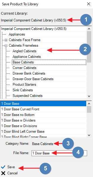
- Displays the current library.
- Select the library category you want to save the product to.
- Displayed the current library category selected.
- Enter a name for the new product.
- Save and Cancel button.
After you have saved a product back to the library or modified library categories, you will need to reload the library to see the changes within the software. You can do this by using the Change Current Library command to switching to another library and then switching back. You can also shut down and restart the program.
Group Products
Align Products

The Align Product command button allows you to move an existing product from one point in the drawing to another point in the drawing no matter what the angle of the final location. This tool is handy if you do not know the angle of a wall that you want to move an existing product to. To use this command, you will need to select four points within the drawing to return the necessary information to Toolbox. First, you select an anchor point on the product, then the point you want to move that anchor point to. Next, you will need to pick an alignment point. This is usually going to be another point on the cabinet that creates an imaginary line from the anchor point. This imaginary line is the same line that will be used to align the product on the new wall. Now the last point is the new alignment point. This point is chosen on one side or the other of the new location’s anchor point. It controls the alignment of the product on the new wall.
Redraw Selected Products

The Redraw Selected Products command button allows you to redraw any number of products in one of four different drawing styles. The available drawing styles are as follows:
- 2D Plan Drawings – Will draw a 2D plan view of the product.
- 2D Plan and Elevation Drawings – Will draw a 2D plan view of the product with the elevation view of the product right on top of the plan view.
- 3D Drawings (Minimal Machining) – Only machining operations that fully cut off a portion of a part will be shown in the drawing. No other machining operations will be drawn.
- 3D Drawings (Minimal Machining and Shelf Holes) – Same as above, but with the addition of shelf hole machining.
- 3D Drawings (Full Machining) – All machining operations will draw, including dados, dowel holes, and any other machining operations.
The default drawing style is 3D Drawings (Minimal Machining). This allows Toolbox to draw products faster. If you need to look at the machining or would like to verify the machining is correct, use the 3D Drawings (Full Machining) option. The drawing style does not affect whether or not the parts will be machined. This is only for drawing purposes.
You can change the default drawing style in the options screen under the AutoCAD tab. Under the Drawing Preference section, you will find these same options. Whichever setting is selected will be how products are drawn from the library.
Edit Design Data

The Edit Design Data command allows you to access the product’s data in the spreadsheet format. This allows you to see all the formulas that drive how a product is created. The spreadsheet is divided into four different sheets. CutParts contains all of the part and machining operations in the product. HardwareParts contains hardware that is assigned to the product. Subassemblies sheet displays all the associated subassembly files. You can access the spreadsheet of a subassembly through the right-click context menu. The last sheet, Prompts, contains all the options that create the Prompts or Product Properties interface. For detailed information about the spreadsheet, review the Working with the Spreadsheet section.
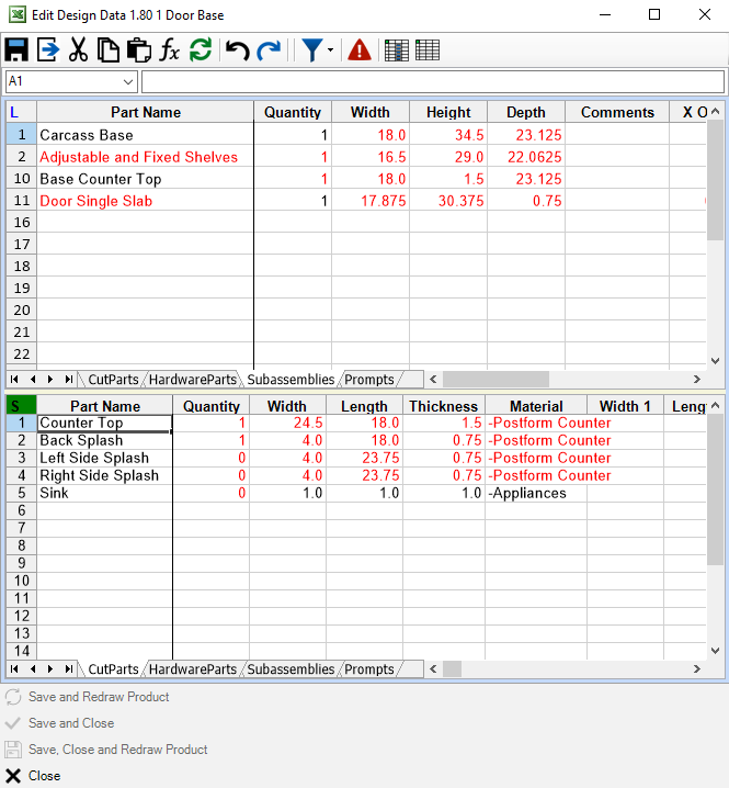
See Understanding the Edit Design Data Interface for more information.
Adjust Wall Length
Mirror Products

The Mirror Product feature incorporates prompt information from the product and should not be mistaken for the AutoCAD mirror command. The feature gives us the ability to mirror products via related prompt value changes triggered from values in the "Mirrored Value" column inside the Edit Design Data "Prompts" worksheet. For example, a Base Cabinet with a Left Finished End will contain a formula in its mirrored value prompt as =Right_Finished_End. A customized product will need formulas created in the prompt for the Mirror Product feature to be utilized.
To use, select the product > select first mirror point > select second mirror point.
Isolate Selected Entities

As the name suggests, this is for getting an entity on its own to make it easier to view.
Hide Selected Entities

Similar to isolating entities, hiding selected entities is helpful for viewing other entities. Hiding an entity will not remove it from the database.
Show Hidden Entities

Undoes Hide Selected Entities.
Related Articles
Recommended Procedure for Working Remotely
The following Procedure for Working Remotely requires that all clients be running the same Microvellum Software Build and Library Build We recommend that you do not try to work remotely with Microvellum and AutoCAD using a Virtual Private Network ...Solid Modeling Tools - Custom Products
Solid Modeling Tools - Custom Products Before using the Custom Product Builder, it is important to determine which type of custom product you will be building. There are five options to select from: Custom Product Starter – This option allows you to ...Solid Modeling Tools - How to Modify the Active 2D Section Drawing to Modify the 3D Product (Tutorial 2: Part 2)
This article continues from Solid Modeling Tools - How to Restore Products from an Existing Drawing and provides information regarding the use of 2D Section Drawings for modifying 3D Products. Click in the left viewport containing the section to ...Solid Modeling Tools - How to Modify a Product by Adding a Wall Arc (Tutorial 4: Part 1)
This is the fourth in a series of articles containing tutorials designed to acquaint you with the basic steps in using the Microvellum Solid Modeling Tools. You may also know these tools as SMT. The steps contained in this tutorial start where ...Using the Group Products Command in Microvellum
Group Products Command Using the "Group Products" command allows you to save multiple products together that you can then add to other projects. The command will remember how the products were positioned and draw them back the same way. Any prompt ...
Recent Articles
Microvellum Release Notes | Build 26.1.0723.641
The following release notes apply to Microvellum build 26.1.0723.641. Function UI Update The Function Arguments interface has received a major visual overhaul to improve the usability, clarity, and visibility of several elements. Input fields are now ...Microvellum Release Notes | Build 26.1.0702.641
Dark Mode Fig. 1: The MV Palette in Dark Mode. To enhance the user experience when working within Microvellum, a new Dark Mode setting has been added to the software. Enabling this will apply a dark theme to most interfaces, allowing for a greater ...Microvellum Foundation Library Release Notes | Build 26.0630
Additions: Added new Fixture product Die Wall Advanced. This product takes the legacy Die Wall products to a new level. More features and advanced parametric abilities: Up to five individual unique subassembly segments, widths controlled via ...Microvellum Foundation Library Release Notes | Build 26.0527
The following release notes apply to the Microvellum Foundation Library build 26.0527. Additions Added new features for the Wood Drawer Box to have reduced sides, sub front, or back. Added 3 new global and subassembly prompts: “Wood Drawer Side ...Microvellum Release Notes | Build 26.1.0529.641
The following release notes apply to Microvellum build 26.1.0529.641. BSB Docking Size Fix An issue was reported to be occurring in Microvellum BSB 2026: when adjusting the size of a docked Microvellum palette, users found that the palette would ...