3DMOVE Command
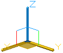
If the default gizmo (DEFAULTGIZMO) is 3D Move, the 3D Move gizmo is displayed whenever you select an object in a view with a 3D visual style. If the visual style is set to 2D Wireframe, the visual style changes to 3D Wireframe for the duration of the command.
The 3D Move gizmo is displayed at the center of the selected 3D object or objects by default. The 3D Move Gizmo shortcut menu offers options for aligning, moving, or changing to another gizmo.
For example, you can also align the 3D Move gizmo with the plane of a face or object by using the Align Gizmo With > Object option on the shortcut menu. The direction of the move operation is then constrained relative to this work plane.
Select Objects
Selects the 3D objects you want to move. When you have selected the objects, press Enter.
When you have selected an object, the gizmo is displayed. You can constrain the movement by clicking one of the following locations on the gizmo:
- Move Along an Axis. Click an axis to constrain the movement to that axis.
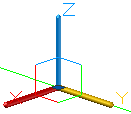
- Move Along a Plane. Click the area between the axes to constrain the movement to that plane.
Stretch Point
When you are specifying the move using the gizmo, sets the new location of the selected objects. Drag and click to move the objects dynamically.
Copy
When you are specifying the move using the gizmo, creates a copy of the selected objects instead of moving them. You can make multiple copies by continuing to specify locations.
Base Point
Specifies the base point of the 3D objects you want to move.
- Second Point. Specifies where the 3D object or objects will be dragged. You can also move the cursor to indicate a direction and then enter a distance.
Displacement
Specifies a relative distance and direction for the placement of the selected 3D objects using coordinate values that you enter at the command prompt.
Powered by AutoCAD®
Related Articles
3DPOLY Command
Creates a 3D polyline. A 3D polyline is a connected sequence of straight line segments created as a single object. 3D polylines can be non-coplanar; however, they cannot include arc segments. The following prompts are displayed: Start Point of ...ACTBASEPOINT Command
Inserts a base point or base point prompt in an action macro. As you record an action macro, you can use this command to insert a prompt for base point input. During playback, the macro pauses to display the prompt and does not continue until a ...PSPACE Command
In a layout, switches from model space in a layout viewport to paper space. As part of designing a layout, you can create objects in paper space. Typically, you insert a title block (see INSERT) and create layout viewports (see VPORTS), which can ...OFFSET Command
Creates concentric circles, parallel lines, and parallel curves. You can offset an object at a specified distance or through a point. After you offset objects, you can trim and extend them as an efficient method to create drawings containing many ...DRAWORDER Command
Changes the draw order of images and other objects. Several options are available that control the order in which overlapping objects are displayed. In addition to the DRAWORDER command, the TEXTTOFRONT command brings all text, dimensions, or ...
Recent Articles
Microvellum Release Notes | Build 26.1.0723.641
The following release notes apply to Microvellum build 26.1.0723.641. Function UI Update The Function Arguments interface has received a major visual overhaul to improve the usability, clarity, and visibility of several elements. Input fields are now ...Microvellum Release Notes | Build 26.1.0702.641
Dark Mode Fig. 1: The MV Palette in Dark Mode. To enhance the user experience when working within Microvellum, a new Dark Mode setting has been added to the software. Enabling this will apply a dark theme to most interfaces, allowing for a greater ...Microvellum Foundation Library Release Notes | Build 26.0630
Additions: Added new Fixture product Die Wall Advanced. This product takes the legacy Die Wall products to a new level. More features and advanced parametric abilities: Up to five individual unique subassembly segments, widths controlled via ...Microvellum Foundation Library Release Notes | Build 26.0527
The following release notes apply to the Microvellum Foundation Library build 26.0527. Additions Added new features for the Wood Drawer Box to have reduced sides, sub front, or back. Added 3 new global and subassembly prompts: “Wood Drawer Side ...Microvellum Release Notes | Build 26.1.0529.641
The following release notes apply to Microvellum build 26.1.0529.641. BSB Docking Size Fix An issue was reported to be occurring in Microvellum BSB 2026: when adjusting the size of a docked Microvellum palette, users found that the palette would ...