ALIGN Command
Aligns objects with other objects in 2D and 3D.
Either one, two, or three pairs of source points and definition points can be specified to move, rotate, or tilt the selected objects, aligning them with points on another object.
Specify either one, two, or three pairs of source points and definition points to align the selected objects.
The following prompts are displayed.
Select the objects to align and press Enter. The next series of prompts asks for source and destination points. The number of point pairs that you specify determines the results.
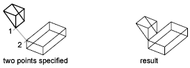
When you select only one source point and destination point pair, the selected objects move in 2D or 3D from the source point (1) to the destination point (2).
When you select two point pairs, you can move, rotate, and scale the selected objects to align with other objects.
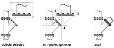
The first set of source and destination points defines the base point for the alignment (1, 2). The second set of points defines the angle of rotation (3, 4).

When you select three point pairs, you can move and rotate the selected objects in 3D to align with other objects.
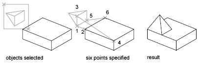
The selected objects move from the source point (1) to the destination point (2).
The selected object is rotated (1 and 3) so that it aligns with the destination object (2 and 4).
The selected object is then rotated again (3 and 5) so that it aligns with the destination object (4 and 6).
- Type ALIGN in the command line and press Enter.
- Select the objects that you want to align.
- Specify a source point and then the corresponding destination point. To rotate the object, specify a second source point followed by a second destination point.
- Press Enter to end the command.
The selected objects are moved from the source point to the destination point, and second and third points, if you specify them, rotate and tilt the selected objects.
Powered by AutoCAD®
Related Articles
3DMOVE Command
In a 3D view, displays the 3D Move gizmo to aid in moving 3D objects a specified distance in a specified direction. With the 3D Move gizmo, you can move selected objects and sub-objects freely or constrain the movement to an axis or plane. If the ...UCS Command
Sets the origin and orientation of the current user coordinate system (UCS). The UCS is a moveable Cartesian coordinate system that establishes the XY work plane, horizontal and vertical directions, axes of rotation, and other useful geometric ...DIM Command
Creates multiple dimensions and types of dimensions with a single command. You can select objects or points on objects to dimension, and then click to place the dimension line. When you hover over an object, the DIM command automatically generates a ...3DALIGN Command
Aligns objects with other objects in 2D and 3D. Specify up to three points on the object to be aligned. Then specify up to three corresponding points for the destination. The following prompts are displayed: Select Objects Selects one or more ...AutoCAD Keyboard Commands
Learning how to use AutoCAD keyboard commands can help you work faster and improve your efficiency. This article lists the abbreviated commands that can be used in AutoCAD (Toolbox). Toggle General Features Ctrl+G Toggle Grid Ctrl+E Cycle isometric ...
Recent Articles
Microvellum Foundation Library Release Notes | Build 26.0527
The following release notes apply to the Microvellum Foundation Library build 26.0527. Additions Added new features for the Wood Drawer Box to have reduced sides, sub front, or back. Added 3 new global and subassembly prompts: “Wood Drawer Side ...Microvellum Release Notes | Build 26.1.0529.641
The following release notes apply to Microvellum build 26.1.0529.641. BSB Docking Size Fix An issue was reported to be occurring in Microvellum BSB 2026: when adjusting the size of a docked Microvellum palette, users found that the palette would ...Adding Custom Hinges and Mounting Plates (Foundation Library)
Hinges and mounting plates are classified as hardware items within the Foundation library, and as such, the process for adding hinges and mounting plates does not differ greatly from other pieces of hardware, though with the variety of cabinet ...Apply Render Materials
The Apply Render Materials interface is a Microvellum function that allows one to assign specific render materials to database materials within one’s material library. Using this interface, one can efficiently control and visually align one’s ...Microvellum Release Notes | Build 26.1.0520.641
The following release notes apply to Microvellum build 26.1.0520.641. Assign Render Material A new option has been added to the Library Specification Groups interface: Assign Render Material. This new interface displays the Microvellum material ...