BREAK Command
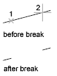
You can create a gap between two specified points on an object, breaking it into two objects. If the points are off of an object, they are automatically projected on to the object. BREAK is often used to create space for a block or text.
The prompts that are displayed depend on how you select the object. If you select the object by using your pointing device, the program both selects the object and treats the selection point as the first break point. At the next prompt, you can continue by specifying the second point or by overriding the first point.
Overrides the original first point where you selected the object with a new point that you specify.
Specifies a second point. The portion of the object is erased between the two points that you specify. If the second point is not on the object, the nearest point on the object is selected; therefore, to break off one end of a line, arc, or polyline, specify the second point beyond the end to be removed.
Lines, arcs, circles, polylines, ellipses, splines, donuts, and several other object types can be split into two objects or have one end removed.
To break selected objects at a single point, use the BREAKATPOINT command.
Related Articles
SPLINE Command
Using the SPLINE Command for the Construction Path in Solid Modeling Tools will result it to break into segments. Creates a smooth curve that passes through or near a set of fit points, or that is defined by the vertices in a control frame. SPLINE ...DIM Command
Creates multiple dimensions and types of dimensions with a single command. You can select objects or points on objects to dimension, and then click to place the dimension line. When you hover over an object, the DIM command automatically generates a ...AutoCAD Keyboard Commands
Learning how to use AutoCAD keyboard commands can help you work faster and improve your efficiency. This article lists the abbreviated commands that can be used in AutoCAD (Toolbox). Toggle General Features Ctrl+G Toggle Grid Ctrl+E Cycle isometric ...3DPOLY Command
Creates a 3D polyline. A 3D polyline is a connected sequence of straight line segments created as a single object. 3D polylines can be non-coplanar; however, they cannot include arc segments. The following prompts are displayed: Start Point of ...ACTBASEPOINT Command
Inserts a base point or base point prompt in an action macro. As you record an action macro, you can use this command to insert a prompt for base point input. During playback, the macro pauses to display the prompt and does not continue until a ...
Recent Articles
Microvellum Release Notes | Build 26.1.0723.641
The following release notes apply to Microvellum build 26.1.0723.641. Function UI Update The Function Arguments interface has received a major visual overhaul to improve the usability, clarity, and visibility of several elements. Input fields are now ...Microvellum Release Notes | Build 26.1.0702.641
Dark Mode Fig. 1: The MV Palette in Dark Mode. To enhance the user experience when working within Microvellum, a new Dark Mode setting has been added to the software. Enabling this will apply a dark theme to most interfaces, allowing for a greater ...Microvellum Foundation Library Release Notes | Build 26.0630
Additions: Added new Fixture product Die Wall Advanced. This product takes the legacy Die Wall products to a new level. More features and advanced parametric abilities: Up to five individual unique subassembly segments, widths controlled via ...Microvellum Foundation Library Release Notes | Build 26.0527
The following release notes apply to the Microvellum Foundation Library build 26.0527. Additions Added new features for the Wood Drawer Box to have reduced sides, sub front, or back. Added 3 new global and subassembly prompts: “Wood Drawer Side ...Microvellum Release Notes | Build 26.1.0529.641
The following release notes apply to Microvellum build 26.1.0529.641. BSB Docking Size Fix An issue was reported to be occurring in Microvellum BSB 2026: when adjusting the size of a docked Microvellum palette, users found that the palette would ...