SPLINE Command

Using the SPLINE Command for the Construction Path in Solid Modeling Tools will result it to break into segments.
Creates a smooth curve that passes through or near a set of fit points, or that is defined by the vertices in a control frame.
SPLINE creates curves called nonuniform rational B-splines (NURBS), referred to as splines for simplicity.
Splines are defined either with fit points, or with control vertices. By default, fit points coincide with the spline, while control vertices define a control frame. Control frames provides a convenient method to shape the spline. Each method has its advantages.
To display or hide the control vertices and control frame, select or deselect the spline, or use CVSHOW and CVHIDE. However, for splines created with control vertices in AutoCAD LT, you can display the control frame only by selecting the spline.
The prompts differ, depending on whether you choose Fit or CV (Control Vertices) as the creation method (Method option).
First Point
Specifies the first point of the spline, either the first fit point or the first control vertex, depending on the current method.Next PointCreates additional spline segments until you press Enter.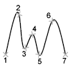 UndoRemoves the last specified point.CloseCloses the spline by defining the last point to be coincident with the first. By default, closed splines are periodic, maintaining curvature continuity (C2) along the entire loop.
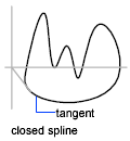
Method
Controls whether the spline is created with fit points or with control vertices. (SPLMETHOD system variable).FitCreates a degree 3 (cubic) B-spline by specifying fit points that the spline must pass through. When the tolerance value is greater than 0, the spline must pass through. When the tolerance value is greater than 0, the spline must be within the specified tolerance distance from each point.Control Vertices (CV)Creates a spline by specifying control vertices. Use this method to create splines of degree 1 (linear), degree 2 (quadratic), degree 3 (cubic), and so on up to degree 10. Adjusting the shape of a spline by moving control vertices often provides better results than moving fit points.
Object
Converts 2D or 3D quadratic or cubic spline-fit polylines to equivalent splines. The original polyline is retained or discarded depending on the setting of the DELOBJ system variable.
Prompts for Splines with Fit Points
The following prompts are specific to the fit point method:
KnotsSpecifies the knot parameterization, one of several computational methods that determines how the component curves between successive fit points within a spline are blended. (SPLKNOTS system variable).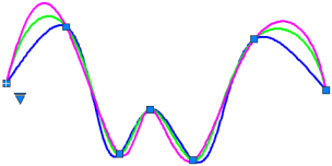
- Chord. (Chord-Length method) Spaces the knots connecting each component curve to be proportional to the distances between each associated pair of fit points. An example is the green curve in the illustration.
- Square Root. (Centripetal method) Spaces the knots connecting each component curve to be proportional to the square root of the distance between each associated pair of fit points. This method usually produces "gentler" curves.
- Uniform. (Equidistant method). Spaces the knows of each component curve to be equal, regardless of the spacing of the fit points. This method often produces curves that overshoot the fit points.
Start TangencySpecifies a tangent condition on the starting point of the spline.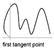 End TangencySpecifies a tangent condition on the ending point of the spline.
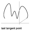 ToleranceSpecifies the distance by which the spline is allowed to deviate from the specified fit points. A tolerance value of 0 requires the resulting spline to pass directly through the fit points. The tolerance value applies to all fit points except the starting and ending fit points, which always have a tolerance of 0.
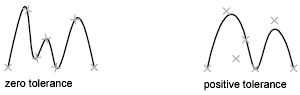
Prompts for Splines with Controls Vertices
The following prompt is specific to the control vertices (CV) method. (SPLMETHOD system variable).
DegreeSets the polynomial degree of the resulting spline. Use this option to create splines of degree 1 (linear), degree 2 (quadratic), degree 3 (cubic), and so on up to degree 10.
Powered by AutoCAD®
Related Articles
REVOLVE Command
Creates a 3D solid or surface by sweeping an object around an axis. Open profiles create surfaces and closed profiles can create either a solid or a surface. The Mode option controls whether a solid or a surface is created. When creating a surface, ...BLEND Command
Creates a spline in the gap between two selected lines or curves. Select each object near an endpoint. The shape of the resulting spline depends on the specified continuity. The lengths of the selected objects remain unchanged. Valid objects ...JOIN Command
Joins the endpoints of linear and curved objects to create a single object. Combines a series of finite linear and open curved objects at their common endpoints to create a single 2D or 3D object. The type of object that results depends on the types ...DIVIDE Command
Creates evenly spaced point objects or blocks along the length or perimeter of an object. The following prompts are displayed: Select Objects to Divide Specifies a single geometric object such as a line, polyline, arc, circle, ellipse, or spline. ...REVSURF Command
Creates a mesh by revolving a profile about an axis. Select a line, arc, circle, or 2D or 3D polyline to sweep in a circular path around a selected axis. The MESHTYPE system variable sets which type of mesh is created. Mesh objects are created by ...
Recent Articles
Microvellum Release Notes | Build 26.1.0723.641
The following release notes apply to Microvellum build 26.1.0723.641. Function UI Update The Function Arguments interface has received a major visual overhaul to improve the usability, clarity, and visibility of several elements. Input fields are now ...Microvellum Release Notes | Build 26.1.0702.641
Dark Mode Fig. 1: The MV Palette in Dark Mode. To enhance the user experience when working within Microvellum, a new Dark Mode setting has been added to the software. Enabling this will apply a dark theme to most interfaces, allowing for a greater ...Microvellum Foundation Library Release Notes | Build 26.0630
Additions: Added new Fixture product Die Wall Advanced. This product takes the legacy Die Wall products to a new level. More features and advanced parametric abilities: Up to five individual unique subassembly segments, widths controlled via ...Microvellum Foundation Library Release Notes | Build 26.0527
The following release notes apply to the Microvellum Foundation Library build 26.0527. Additions Added new features for the Wood Drawer Box to have reduced sides, sub front, or back. Added 3 new global and subassembly prompts: “Wood Drawer Side ...Microvellum Release Notes | Build 26.1.0529.641
The following release notes apply to Microvellum build 26.1.0529.641. BSB Docking Size Fix An issue was reported to be occurring in Microvellum BSB 2026: when adjusting the size of a docked Microvellum palette, users found that the palette would ...