CHAMFER Command
Bevels or chamfers the edges of two 2D objects or the adjacent faces of a 3D solid. A bevel or chamfer is an angle line that meets the endpoints of two straight 2D objects.
The distance and angles that you specify are applied in the order that you select the objects.
Create 2D Chamfers
A bevel or chamfer can be defined by selecting two objects of the same or different object types: lines, polylines, rays, and xlines.
If the two selected objects are on the same layers, the line defined is created on that layer. Otherwise, the line is created on the current layer. The layer affects object properties including color and linetype.
The following prompts are displayed when creating a 2D chamfer.
Select the first of two objects or the first line segment of a 2D polyline to define the chamfer.
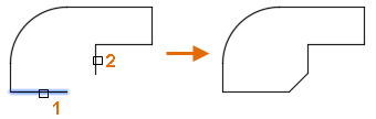
Select the second object or line segment of a 2D polyline to define the chamfer.
You can also hold down the Shift key before selecting the second object or line segment of a 2D polyline to extend or trim the selected objects to from a sharp corner. While Shift is held down, a temporary value of zero is assigned to the current chamfer distance and angle values.
If the selected objects are straight line segments of a 2D polyline, the line segments can be adjacent to each other or separated by one other segment. When the selected segments are separated by a segment, the segment that separates them is removed and replaced with the chamfer.
 Adding a chamfer or bevel to a hatch boundary that was defined with individual objects results in the removal of hatch associativity. If the hatch boundary was defined from a polyline, associativity is maintained.
Reverses the previous action in the command.
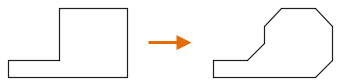
Inserts a chamfer line at each vertex of a 2D polyline where two straight line segments meet. The chamfer lines become new segments of the polyline, unless the Trim option is set to No Trim.
Line segments that are too short to accommodate the chamfer distance are not modified.
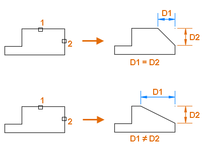
Sets the chamfer distances from the intersecting points of the first and second objects.
If both distances are set to zero, the selected objects or line segments are extended or trimmed so they intersect.
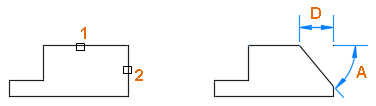
Sets the chamfer distance from the intersecting point of the selected objects and the XY angle from the first object or line segment.
If both values are set to zero, the selected objects or line segments are extended or trimmed so they intersect.
Controls whether the selected objects are trimmed to meet the endpoints of the chamfer line.
- Trim - Selected objects or line segments are trimmed to meet the endpoints of the chamfer line. If the selected objects or line segments do not intersect with the chamfer line, they are extended or trimmed before the chamfer line is added.
- No Trim - Selected objects or line segments are not trimmed before the chamfer line is added.
Controls how the chamfer line is calculated from the intersecting point of the selected objects or line segments.
- Distance - Chamfer line is defined by two distances.
- Angle - Chamfer line is defined by a distance and an angle.
Allows for the beveling of more than one set of objects.
Related Articles
RECTANG Command
Creates a rectangular polyline. Creates a closed rectangular polyline from the specified parameters such as its diagonal corner points, dimensions, area, and type of corners. The following prompts are displayed: Current settings: Rotation = 0 ...AutoCAD Keyboard Commands
Learning how to use AutoCAD keyboard commands can help you work faster and improve your efficiency. This article lists the abbreviated commands that can be used in AutoCAD (Toolbox). Toggle General Features Ctrl+G Toggle Grid Ctrl+E Cycle isometric ...Basic 2D Commands
Basic 2D Commands To execute an AutoCAD command, type the command (or quick-key) in the command line. The command line is located at the bottom of the drawing area. Some commands require additional steps, or subcommands, the next step for the command ...3DPOLY Command
Creates a 3D polyline. A 3D polyline is a connected sequence of straight line segments created as a single object. 3D polylines can be non-coplanar; however, they cannot include arc segments. The following prompts are displayed: Start Point of ...ACTBASEPOINT Command
Inserts a base point or base point prompt in an action macro. As you record an action macro, you can use this command to insert a prompt for base point input. During playback, the macro pauses to display the prompt and does not continue until a ...
Recent Articles
Microvellum Release Notes | Build 26.1.0723.641
The following release notes apply to Microvellum build 26.1.0723.641. Function UI Update The Function Arguments interface has received a major visual overhaul to improve the usability, clarity, and visibility of several elements. Input fields are now ...Microvellum Release Notes | Build 26.1.0702.641
Dark Mode Fig. 1: The MV Palette in Dark Mode. To enhance the user experience when working within Microvellum, a new Dark Mode setting has been added to the software. Enabling this will apply a dark theme to most interfaces, allowing for a greater ...Microvellum Foundation Library Release Notes | Build 26.0630
Additions: Added new Fixture product Die Wall Advanced. This product takes the legacy Die Wall products to a new level. More features and advanced parametric abilities: Up to five individual unique subassembly segments, widths controlled via ...Microvellum Foundation Library Release Notes | Build 26.0527
The following release notes apply to the Microvellum Foundation Library build 26.0527. Additions Added new features for the Wood Drawer Box to have reduced sides, sub front, or back. Added 3 new global and subassembly prompts: “Wood Drawer Side ...Microvellum Release Notes | Build 26.1.0529.641
The following release notes apply to Microvellum build 26.1.0529.641. BSB Docking Size Fix An issue was reported to be occurring in Microvellum BSB 2026: when adjusting the size of a docked Microvellum palette, users found that the palette would ...