EXTRUDE Command
Creates a 3D solid from an object that encloses an area, or a 3D surface from an object with open ends.
Objects can be extruded orthogonally from the plane of the source object, in a specified direction, or along a selected path. You can also specify a taper angle.
The DELOBJ system variable controls whether the source objects or selected path are automatically deleted when the solid or surface is created, or whether you are prompted.
|
Object Type |
Can be Extruded? |
Can be Extrusion Path? |
Comments |
|
3D Faces |
✓ |
|
|
|
Arcs |
✓ |
✓ |
|
|
Circles |
✓ |
✓ |
|
|
Ellipses |
✓ |
✓ |
|
|
Elliptical Arcs |
✓ |
✓ |
|
|
Helixes |
✓ |
✓ |
|
|
Lines |
✓ |
✓ |
|
|
Meshes: Faces |
|
|
Use the MESHEXTRUDE command. |
|
Meshes: Edges |
|
|
Press Ctrl and use the gizmo to change the location of the edge. |
|
2D Polylines |
✓ |
✓ |
2D polylines with crossing segments cannot be extruded.
Thickness and width are ignored.
The extrusion extends from the center line. |
|
3D Polylines |
✓ |
✓ |
|
|
Regions |
✓ |
|
|
|
2D Solids |
✓ |
|
|
| 3D Solids: Edges |
✓ |
✓ |
|
|
3D Solids: Faces |
✓ |
|
|
|
Splines: 2D and 3D |
✓ |
✓ |
|
|
Surfaces: Edges |
X |
✓ |
|
|
Surfaces: Planar and Non-Planar |
✓ |
|
|
Objects to Extrude
Specifies the objects to extrude.

 Select face and edge subobjects by pressing Ctrl while you select them.
Mode
Controls whether the extruded object is a solid or a surface.
Surfaces are extruded as either NURBS surfaces or procedural surfaces, depending on the SURFACEMODELINGMODE system variable.
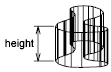
Height of Extrusion
Extrudes selected objects along the positive or negative Z axis. The direction is based on the UCS that was current when the object was created, or (for multiple selections) on the original UCS of the most recently created object.
Direction
Specifies the length and direction of the extrusion with two specified points. (The direction cannot be parallel to the plane of the sweep curve created by the extrusion.)
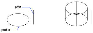
Path
Specifies the extrusion path based on a selected object. The path is moved to the centroid of the profile. Then the profile of the selected object is extruded along the chosen path to create solids or surfaces.
Select face and edge subobjects by pressing Ctrl while you select them.
The path should not lie on the same plane as the object, nor should the path have areas of high curvature.
The extrusion starts from the plane of the object and maintains its orientation relative to the path.
If the path contains segments that are not tangent, the program extrudes the object along each segment and then miters the joint along the plane bisecting the angle formed by the segments. If the path is closed, the object should lie on the miter plane. This allows the start and end sections of the solid to match up. If the object is not on the miter plane, the object is rotated until it is on the miter plane.
Objects with multiple loops are extruded so that all of the loops appear on the same plane at the end section of the extruded solid.
Taper Angle
Specifies the taper angle for the extrusion.
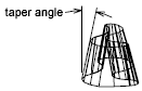
Positive angles taper in from the base object. Negative angles taper out. The default angle, 0, extrudes a 2D object perpendicular to its 2D plane. All selected objects and loops are tapered to the same value.
Specifying a large taper angle or a long extrusion height can cause the object or portions of the object to taper to a point before reaching the extrusion height.
Individual loops of a region are always extruded to the same height.
When an arc is part of a tapered extrusion, the angle of the arc remains constant, and the radius of the arc changes.
- Angle of Taper - Specifies the taper between -90 and 90+ degrees.
- Specify Two Points - Specifies the taper angle based on two specified points. The taper angle is the distance between the two specified points.
Drag the cursor horizontally to specify and preview the taper angle. You can also drag the cursor to adjust and preview the height of the extrusion. The dynamic input origin should be placed on the extruded shape, on the projection of the point to the shape.
When you select the extruded object, the position of the taper grip is the correspondent point of the dynamic input origin on the top face of the extrusion.
Expression
Enter a formula or equation to specify the extrusion height.
Powered by AutoCAD®
Related Articles
REVOLVE Command
Creates a 3D solid or surface by sweeping an object around an axis. Open profiles create surfaces and closed profiles can create either a solid or a surface. The Mode option controls whether a solid or a surface is created. When creating a surface, ...AutoCAD Keyboard Commands
Learning how to use AutoCAD keyboard commands can help you work faster and improve your efficiency. This article lists the abbreviated commands that can be used in AutoCAD (Toolbox). Toggle General Features Ctrl+G Toggle Grid Ctrl+E Cycle isometric ...3DPOLY Command
Creates a 3D polyline. A 3D polyline is a connected sequence of straight line segments created as a single object. 3D polylines can be non-coplanar; however, they cannot include arc segments. The following prompts are displayed: Start Point of ...ACTBASEPOINT Command
Inserts a base point or base point prompt in an action macro. As you record an action macro, you can use this command to insert a prompt for base point input. During playback, the macro pauses to display the prompt and does not continue until a ...PSPACE Command
In a layout, switches from model space in a layout viewport to paper space. As part of designing a layout, you can create objects in paper space. Typically, you insert a title block (see INSERT) and create layout viewports (see VPORTS), which can ...
Recent Articles
Microvellum Release Notes | Build 26.1.0723.641
The following release notes apply to Microvellum build 26.1.0723.641. Function UI Update The Function Arguments interface has received a major visual overhaul to improve the usability, clarity, and visibility of several elements. Input fields are now ...Microvellum Release Notes | Build 26.1.0702.641
Dark Mode Fig. 1: The MV Palette in Dark Mode. To enhance the user experience when working within Microvellum, a new Dark Mode setting has been added to the software. Enabling this will apply a dark theme to most interfaces, allowing for a greater ...Microvellum Foundation Library Release Notes | Build 26.0630
Additions: Added new Fixture product Die Wall Advanced. This product takes the legacy Die Wall products to a new level. More features and advanced parametric abilities: Up to five individual unique subassembly segments, widths controlled via ...Microvellum Foundation Library Release Notes | Build 26.0527
The following release notes apply to the Microvellum Foundation Library build 26.0527. Additions Added new features for the Wood Drawer Box to have reduced sides, sub front, or back. Added 3 new global and subassembly prompts: “Wood Drawer Side ...Microvellum Release Notes | Build 26.1.0529.641
The following release notes apply to Microvellum build 26.1.0529.641. BSB Docking Size Fix An issue was reported to be occurring in Microvellum BSB 2026: when adjusting the size of a docked Microvellum palette, users found that the palette would ...