LINE Command
Create a series of contiguous line segments. Each segment is a line object that can be edited separately.
The following prompts are displayed:
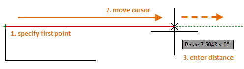
Specify First Point
Sets the starting point for the line. Click a point location. With object snaps or grid snap turned on, the points will be placed precisely. You can also enter coordinates. If instead, you press Enter at the prompt, a new line starts from the endpoint of the most recently created line, polyline, or arc. If the most recently created object is an arc, its endpoint defines the starting point of the line. The line is tangent to the arc.
Specify Next Point
Specifies the endpoint of the line segment. You can also use polar and object snap tracking together with direct distance entry.
Using a Specific Coordinate
- If dynamic input is on: Type the pound sign (#) followed by the X-value, a comma, then the Y-value, for example #4.0,6.75.
- If dynamic input is off: Type the X value, a comma, then the Y value, for example 4.0,6.75.
 When dynamic input is on, relative coordinates are the default. When dynamic input is off, absolute coordinates are the default. Press F12 to turn dynamic input on or off.
Using a Relative Coordinate
A relative coordinate specifies the distance and direction from the previous coordinate.
- If dynamic input is on: Type the X-value, a comma, then the Y-value, for example 4.0,6.75.
- If dynamic input is off: Type the at sign (@) followed by the X-value, a comma, then the Y-value, for example @4.0,6.75.
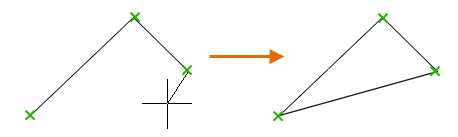
Close
Connects the first and last segments.
Undo
Removes the most recent segment of a line sequence.
Powered by AutoCAD®
Related Articles
About Positioning the Command Window
Change the position and display of the command window to suit the way you work. Docking the Command Window A docked command window is the same width as the application window. It is displayed in a fixed location above or below the drawing area. ...3DPOLY Command
Creates a 3D polyline. A 3D polyline is a connected sequence of straight line segments created as a single object. 3D polylines can be non-coplanar; however, they cannot include arc segments. The following prompts are displayed: Start Point of ...OFFSET Command
Creates concentric circles, parallel lines, and parallel curves. You can offset an object at a specified distance or through a point. After you offset objects, you can trim and extend them as an efficient method to create drawings containing many ...PDFIMPORT Command
Imports the objects in a PDF file or an attached PDF underlay from the command line. Options are provided for selecting either a PDF underlay or for specifying a file. The following prompts are displayed: File - Opens a standard file selection ...TRIM Command
Trim objects to meet the edges of other objects. To trim objects, click TRIM or type TRIM in the command line and press Enter. Overview There are two modes that you can use to trim objects, Quick mode and Standard mode. Quick Mode: To trim ...
Recent Articles
Microvellum Release Notes | Build 26.1.0723.641
The following release notes apply to Microvellum build 26.1.0723.641. Function UI Update The Function Arguments interface has received a major visual overhaul to improve the usability, clarity, and visibility of several elements. Input fields are now ...Microvellum Release Notes | Build 26.1.0702.641
Dark Mode Fig. 1: The MV Palette in Dark Mode. To enhance the user experience when working within Microvellum, a new Dark Mode setting has been added to the software. Enabling this will apply a dark theme to most interfaces, allowing for a greater ...Microvellum Foundation Library Release Notes | Build 26.0630
Additions: Added new Fixture product Die Wall Advanced. This product takes the legacy Die Wall products to a new level. More features and advanced parametric abilities: Up to five individual unique subassembly segments, widths controlled via ...Microvellum Foundation Library Release Notes | Build 26.0527
The following release notes apply to the Microvellum Foundation Library build 26.0527. Additions Added new features for the Wood Drawer Box to have reduced sides, sub front, or back. Added 3 new global and subassembly prompts: “Wood Drawer Side ...Microvellum Release Notes | Build 26.1.0529.641
The following release notes apply to Microvellum build 26.1.0529.641. BSB Docking Size Fix An issue was reported to be occurring in Microvellum BSB 2026: when adjusting the size of a docked Microvellum palette, users found that the palette would ...