OFFSET Command
Creates concentric circles, parallel lines, and parallel curves.
You can offset an object at a specified distance or through a point. After you offset objects, you can trim and extend them as an efficient method to create drawings containing many parallel lines and curves.
The OFFSET command repeats for convenience. To exit the command, press Enter.
The following prompts are displayed:
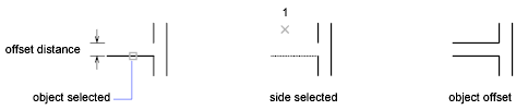
Offset Distance
Creates an object at a specified distance from an existing object.
Exit
Exits the OFFSET command.
Multiple
Enters the Multiple offset mode, which repeats the offset operation using the current offset distance.
Undo
Reverses the previous offset.
Through
Creates an object passing through a specified point.
 For best results when you offset a polyline with corners, specify the through point near the midpoint of a line segment, not near a corner.
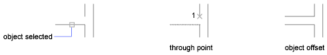
- Exit
- Multiple
- Undo
Erase
Erases the source object after it is offset.
Layer
Determines whether offset objects are created on the current layer or on the layer of the source object.
Powered by AutoCAD®
Related Articles
PRESSPULL Command
Dynamically modifies objects by extrusion and offset. Get visual feedback as you move the cursor after selecting a 2D object, an area formed by a closed boundary or a 3D solid face. The press or pull behavior responds to the type of object you ...REVOLVE Command
Creates a 3D solid or surface by sweeping an object around an axis. Open profiles create surfaces and closed profiles can create either a solid or a surface. The Mode option controls whether a solid or a surface is created. When creating a surface, ...DIM Command
Creates multiple dimensions and types of dimensions with a single command. You can select objects or points on objects to dimension, and then click to place the dimension line. When you hover over an object, the DIM command automatically generates a ...STRETCH Command
Stretches objects crossed by a selection window or polygon. Objects that are partially enclosed by a crossing window are stretched. Objects that are completely enclosed within the crossing window, or that are selected individually, are moved rather ...REVSURF Command
Creates a mesh by revolving a profile about an axis. Select a line, arc, circle, or 2D or 3D polyline to sweep in a circular path around a selected axis. The MESHTYPE system variable sets which type of mesh is created. Mesh objects are created by ...
Recent Articles
Microvellum Release Notes | Build 26.1.0723.641
The following release notes apply to Microvellum build 26.1.0723.641. Function UI Update The Function Arguments interface has received a major visual overhaul to improve the usability, clarity, and visibility of several elements. Input fields are now ...Microvellum Release Notes | Build 26.1.0702.641
Dark Mode Fig. 1: The MV Palette in Dark Mode. To enhance the user experience when working within Microvellum, a new Dark Mode setting has been added to the software. Enabling this will apply a dark theme to most interfaces, allowing for a greater ...Microvellum Foundation Library Release Notes | Build 26.0630
Additions: Added new Fixture product Die Wall Advanced. This product takes the legacy Die Wall products to a new level. More features and advanced parametric abilities: Up to five individual unique subassembly segments, widths controlled via ...Microvellum Foundation Library Release Notes | Build 26.0527
The following release notes apply to the Microvellum Foundation Library build 26.0527. Additions Added new features for the Wood Drawer Box to have reduced sides, sub front, or back. Added 3 new global and subassembly prompts: “Wood Drawer Side ...Microvellum Release Notes | Build 26.1.0529.641
The following release notes apply to Microvellum build 26.1.0529.641. BSB Docking Size Fix An issue was reported to be occurring in Microvellum BSB 2026: when adjusting the size of a docked Microvellum palette, users found that the palette would ...