REVSURF Command
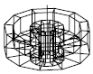
Creates a mesh by revolving a profile about an axis.
Select a line, arc, circle, or 2D or 3D polyline to sweep in a circular path around a selected axis.
The MESHTYPE system variable sets which type of mesh is created. Mesh objects are created by default. Set the variable to 0 to create legacy polyface or polygon mesh.
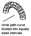
The density of the generated mesh is controlled by the SURFTAB1 and SURFTAB2 system variables. SURFTAB1 specifies the number of tabulation lines that are drawn in the direction of revolution. If the path curve is a line, arc, circle, or spline-fit polyline, SURFTAB2 specifies the number of tabulation lines that are drawn to divide it into equal-sized intervals. If the path curve is a polyline that has not been spline fit, tabulation lines are drawn at the ends of straight segments, and each arc segment is divided into the number of intervals specified by SURFTAB2.
The following prompts are displayed:
Current wireframe density: SURFTAB1=current SURFTAB2=current
Object to Revolve
Select a line, arc, circle, or 2D or 3D polyline.
Object that Defines Axis of Revolution
Select a line or open 2D or 3D polyline. The axis direction cannot be parallel to the plane of the original object.
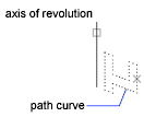
The path curve is swept about the selected axis to define the mesh. The path curve defines the N direction of the mesh. Selecting a circle or a closed polyline as the path curve closes the mesh in the N direction.
The vector from the first to the last vertex of the polyline determines the rotation axis. Any intermediate vertices are ignored. The axis of revolution determines the M direction of the mesh.
Start Angle
If set to a nonzero value, starts the mesh of revolution at an offset from the generating path curve.
Specifying a start angle starts the mesh of revolution at an offset from the generating path curve.
Included Angle
Specifies how far about the axis of revolution the mesh extends. The included angle is the distance through which the path curve is swept.
Entering an included angle that is less than a full circle prevents the circle from closing.
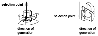
The point you use to select the axis of revolution affects the direction of revolution. The mesh in the following example was created by specifying a start angle of 0 degrees and an included angle of 90 degrees.
Powered by AutoCAD®
Related Articles
AutoCAD Keyboard Commands
Learning how to use AutoCAD keyboard commands can help you work faster and improve your efficiency. This article lists the abbreviated commands that can be used in AutoCAD (Toolbox). Toggle General Features Ctrl+G Toggle Grid Ctrl+E Cycle isometric ...3DPOLY Command
Creates a 3D polyline. A 3D polyline is a connected sequence of straight line segments created as a single object. 3D polylines can be non-coplanar; however, they cannot include arc segments. The following prompts are displayed: Start Point of ...ACTBASEPOINT Command
Inserts a base point or base point prompt in an action macro. As you record an action macro, you can use this command to insert a prompt for base point input. During playback, the macro pauses to display the prompt and does not continue until a ...PSPACE Command
In a layout, switches from model space in a layout viewport to paper space. As part of designing a layout, you can create objects in paper space. Typically, you insert a title block (see INSERT) and create layout viewports (see VPORTS), which can ...OFFSET Command
Creates concentric circles, parallel lines, and parallel curves. You can offset an object at a specified distance or through a point. After you offset objects, you can trim and extend them as an efficient method to create drawings containing many ...
Recent Articles
Microvellum Release Notes | Build 26.1.0723.641
The following release notes apply to Microvellum build 26.1.0723.641. Function UI Update The Function Arguments interface has received a major visual overhaul to improve the usability, clarity, and visibility of several elements. Input fields are now ...Microvellum Release Notes | Build 26.1.0702.641
Dark Mode Fig. 1: The MV Palette in Dark Mode. To enhance the user experience when working within Microvellum, a new Dark Mode setting has been added to the software. Enabling this will apply a dark theme to most interfaces, allowing for a greater ...Microvellum Foundation Library Release Notes | Build 26.0630
Additions: Added new Fixture product Die Wall Advanced. This product takes the legacy Die Wall products to a new level. More features and advanced parametric abilities: Up to five individual unique subassembly segments, widths controlled via ...Microvellum Foundation Library Release Notes | Build 26.0527
The following release notes apply to the Microvellum Foundation Library build 26.0527. Additions Added new features for the Wood Drawer Box to have reduced sides, sub front, or back. Added 3 new global and subassembly prompts: “Wood Drawer Side ...Microvellum Release Notes | Build 26.1.0529.641
The following release notes apply to Microvellum build 26.1.0529.641. BSB Docking Size Fix An issue was reported to be occurring in Microvellum BSB 2026: when adjusting the size of a docked Microvellum palette, users found that the palette would ...