STRETCH Command
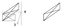
Stretches objects crossed by a selection window or polygon.
Objects that are partially enclosed by a crossing window are stretched. Objects that are completely enclosed within the crossing window, or that are selected individually, are moved rather than stretched.
The following prompts are displayed:
Select Objects
Specifies the portion of the object that you want to stretch. Use the cpolygon option or the crossing object selection method. Press Etner when the selection is complete.

STRETCH moves only the vertices and endpoints that lie inside the crossing selection, leaving those outside unchanged. STRETCH does not modify 3D solids, polyline width, tangent, or curve-fitting information.
Base Point
Specifies the base point from which the offset for the stretch is calculated. This base point can be outside the area being stretched.
Second Point
Specifies a second point that defines the distance and direction of the stretch. The distance and direction of this point from the base point defines how far and in what direction the selected portions of the object will be stretched.
Use First Point as Displacement
Specifies that the stretch distance and direction will be based on the distance and direction of the base point you specified from the 0, 0, 0 coordinates in the drawing.
Displacement
Specifies the relative distance and direction of the stretch.
- To set a displacement based on the relative distance from the current location, enter distances in X, Y, Z format. For example, enter 5, 4, 0 to stretch the selection to a point that is 5 units along the X axis and 4 units along the Y axis from the original point.
- To set the displacement based on the distance and direction from the 0, 0, 0 coordinates in the drawing, click a location in the drawing area. For example, click a point at 1, 2, 0 to stretch the selection to a point that is 1 unit along the X axis and 2 units along the Y axis from its current location.
Powered by AutoCAD®
Related Articles
3DMOVE Command
In a 3D view, displays the 3D Move gizmo to aid in moving 3D objects a specified distance in a specified direction. With the 3D Move gizmo, you can move selected objects and sub-objects freely or constrain the movement to an axis or plane. If the ...AutoCAD Keyboard Commands
Learning how to use AutoCAD keyboard commands can help you work faster and improve your efficiency. This article lists the abbreviated commands that can be used in AutoCAD (Toolbox). Toggle General Features Ctrl+G Toggle Grid Ctrl+E Cycle isometric ...Microvellum Commands vs AutoCAD Commands
Microvellum AC, as a software based in AutoCAD, possesses the full range of AutoCAD commands for use in accessing AutoCAD functions, such as drawing shapes, opening menus, altering the dimensions of polylines, etc. However, it should be noted that ...Basic 2D Commands
Basic 2D Commands To execute an AutoCAD command, type the command (or quick-key) in the command line. The command line is located at the bottom of the drawing area. Some commands require additional steps, or subcommands, the next step for the command ...3DPOLY Command
Creates a 3D polyline. A 3D polyline is a connected sequence of straight line segments created as a single object. 3D polylines can be non-coplanar; however, they cannot include arc segments. The following prompts are displayed: Start Point of ...
Recent Articles
Microvellum Release Notes | Build 26.1.0723.641
The following release notes apply to Microvellum build 26.1.0723.641. Function UI Update The Function Arguments interface has received a major visual overhaul to improve the usability, clarity, and visibility of several elements. Input fields are now ...Microvellum Release Notes | Build 26.1.0702.641
Dark Mode Fig. 1: The MV Palette in Dark Mode. To enhance the user experience when working within Microvellum, a new Dark Mode setting has been added to the software. Enabling this will apply a dark theme to most interfaces, allowing for a greater ...Microvellum Foundation Library Release Notes | Build 26.0630
Additions: Added new Fixture product Die Wall Advanced. This product takes the legacy Die Wall products to a new level. More features and advanced parametric abilities: Up to five individual unique subassembly segments, widths controlled via ...Microvellum Foundation Library Release Notes | Build 26.0527
The following release notes apply to the Microvellum Foundation Library build 26.0527. Additions Added new features for the Wood Drawer Box to have reduced sides, sub front, or back. Added 3 new global and subassembly prompts: “Wood Drawer Side ...Microvellum Release Notes | Build 26.1.0529.641
The following release notes apply to Microvellum build 26.1.0529.641. BSB Docking Size Fix An issue was reported to be occurring in Microvellum BSB 2026: when adjusting the size of a docked Microvellum palette, users found that the palette would ...