CHANGE Command
Changes the properties of existing objects.
The following prompts are displayed:
If you select lines and other changeable objects in the same selection set, you get varying results depending on the object selection sequence. The easiest way to use CHANGE is to select only lines in a selection set or select only objects other than lines in a selection set.
Except for zero-thickness lines, the objects selected must be parallel to the current user coordinate system (UCS).
Changes the selected objects. The result depends on the type of objects you select.
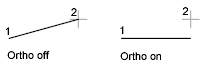
Lines
Moves the endpoints of the selected lines that are closest to the change point to the new point, unless Ortho mode is on. If Ortho mode is on, the selected lines are modified so that they become parallel to either the X or the Y axis; their endpoints are not moved to the specified coordinate.
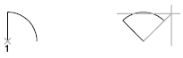
Circles
Changes the circle radius. If you selected more than one circle, the prompt is repeated for the next circle.

Text
Changes text location and other properties.
Specify New Text Insertion Point
Relocates the text.
Attribute Definitions
Changes the text and text properties of an attribute that is not part of a block.
Blocks
Changes the location or rotation of a block.
Specifying a new location relocates the block. Pressing Enter leaves the block in its original location.
Modifies properties of existing objects.
 The Plotstyle option is displayed only when you are using named plot styles.
You can change several properties at a time. The Enter Property to Change prompt is redisplayed after each option is completed.
Color
Changes the color of the selected objects.
For example, to change a color to green, enter green or 3. If you enter bylayer, the object assumes the color of the layer on which it is located. If you enter byblock, the object inherits the color of the block of which it is a component.
- True Color. Specifies a true color to be used for the selected object. The integer values range from 0 to 255 separated by commas.
- Color Book. Specifies a color from a loaded color book to be used for the selected object.
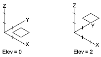
Elev
Changes the Z-axis elevation of 2D objects.
You can change the elevation of an object only if all its points have the same Z value.
Layer
Changes the layer of the selected objects.
Ltype
Changes the linetype of the selected objects.
If the new linetype is not loaded, the program tries to load it from the standard linetype library file acad.lin for AutoCAD or acadlt.lin for AutoCAD LT. If this procedure fails, use LINETYPE to load the linetype.

Ltscale
Changes the linetype scale factor of the selected objects.
Lweight
Changes the lineweight of the selected objects. Lineweight values are predefined values. If you enter a value that is not a predefined value, the closest predefined lineweight is assigned to the selected objects.
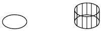
Thickness
Changes the Z-direction thickness of 2D objects.
Changing the thickness of a 3D polyline, dimension, or layout viewport object has no effect.
Transparency
Changes the transparency level of selected objects.
Set the transparency to ByLayer or ByBlock, or enter a value from 0 to 90.
Material
Changes the material of the selected objects if a material is attached.
Annotative
Changes the annotative property of the selected objects.
Powered by AutoCAD®
Related Articles
DRAWORDER Command
Changes the draw order of images and other objects. Several options are available that control the order in which overlapping objects are displayed. In addition to the DRAWORDER command, the TEXTTOFRONT command brings all text, dimensions, or ...ACTBASEPOINT Command
Inserts a base point or base point prompt in an action macro. As you record an action macro, you can use this command to insert a prompt for base point input. During playback, the macro pauses to display the prompt and does not continue until a ...LAYISO Command
Hides or locks all layers except those of the selected objects. All layers except the layers of the selected objects are either turned off, frozen in the current layout viewport, or locked, depending on the current setting. The layers that remain ...HATCH Command
Fills an enclosed area or selected objects with a hatch pattern, solid fill, or gradient fill. When the ribbon is active, the Hatch Creation contextual tab is displayed. When the ribbon is off, the Hatch and Gradient dialog box is displayed. If you ...TRIM Command
Trim objects to meet the edges of other objects. To trim objects, click TRIM or type TRIM in the command line and press Enter. Overview There are two modes that you can use to trim objects, Quick mode and Standard mode. Quick Mode: To trim ...
Recent Articles
Microvellum Release Notes | Build 26.1.0723.641
The following release notes apply to Microvellum build 26.1.0723.641. Function UI Update The Function Arguments interface has received a major visual overhaul to improve the usability, clarity, and visibility of several elements. Input fields are now ...Microvellum Release Notes | Build 26.1.0702.641
Dark Mode Fig. 1: The MV Palette in Dark Mode. To enhance the user experience when working within Microvellum, a new Dark Mode setting has been added to the software. Enabling this will apply a dark theme to most interfaces, allowing for a greater ...Microvellum Foundation Library Release Notes | Build 26.0630
Additions: Added new Fixture product Die Wall Advanced. This product takes the legacy Die Wall products to a new level. More features and advanced parametric abilities: Up to five individual unique subassembly segments, widths controlled via ...Microvellum Foundation Library Release Notes | Build 26.0527
The following release notes apply to the Microvellum Foundation Library build 26.0527. Additions Added new features for the Wood Drawer Box to have reduced sides, sub front, or back. Added 3 new global and subassembly prompts: “Wood Drawer Side ...Microvellum Release Notes | Build 26.1.0529.641
The following release notes apply to Microvellum build 26.1.0529.641. BSB Docking Size Fix An issue was reported to be occurring in Microvellum BSB 2026: when adjusting the size of a docked Microvellum palette, users found that the palette would ...