SNAP Command
Restricts cursor movement to specified intervals.
The following prompts are displayed:
Snap Spacing
Activates Snap mode with the value you specify.
On
Activates Snap mode using the current settings of the snap grid.
Off
Turns off Snap mode but retains the current settings.
Aspect
Specifies different spacing in the X and Y directions.
Legacy
Specifying Yes results in legacy behavior. The cursor snaps the snap grid at all times.
Specifying No results in modern behavior. The cursor snaps the snap grid only when an operation is in progress.
Style
Specifies the format of the snap grid, which is Standard or Isometric.
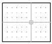
Standard
Sets a rectangular snap grid that is paralleled to the XY plane of the current UCS. X and Y spacing may differ.
Spacing
Specifies the overall spacing of the snap grid.
Aspect
Specifies the horizontal and vertical spacing of the snap grid separately.
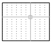
Isometric
Sets an isometric snap grid, in which the snap locations are initially at 30-degree and 150-degree angles. Isometric snap cannot have different Aspect values. The lined grid does not follow the isometric snap grid.
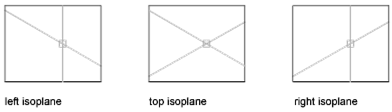
ISOPLANE determines whether the crosshairs lie in the top isometric plane (30- and 150-degree angles), the left isoplane (90- and 150-degree angles), or the right isoplane (30- and 90-degree angles).
Type
Specifies the snap type, polar or rectangular. This setting is also controlled by the SNAPTYPE system variable.
Polar
Sets the polar angle increment. (POLARANG system variable).
Grid
Sets the snap to Grid. When you specify points, the cursor snaps along vertical or horizontal grid points.
Powered by AutoCAD®
Related Articles
ISODRAFT Command
Turns isometric drafting settings on or off, and specifies the current 2D isometric drafting plane. The ISODRAFT command supersedes the ISOPLANE command. The primary advantage of ISODRAFT is that when it is turned on or off, all related settings are ...EDGE Command
Changes the visibility of 3D face edges. This command only affects objects created using the 3DFACE command. The following prompts are displayed. Edge of 3D Face to Toggle Visibility Controls the visibility of the edges you select. If the edges ...3DFACE Command
Creates a three-sided or four-sided surface in 3D space. After entering the last two points for a 3D face, the command repeats automatically using the two points as the first two points of the next 3D face. For example: The following prompts are ...POLYGON Command
Creates an equilateral closed polyline. You specify the number of sides of the polygon and whether it is inscribed or circumscribed. The following prompts are displayed: Number of Sides Specifies the number of sides in the polygon (3-1024). ...LINE Command
Create a series of contiguous line segments. Each segment is a line object that can be edited separately. The following prompts are displayed: Specify First Point Sets the starting point for the line. Click a point location. With object snaps or ...
Recent Articles
Microvellum Release Notes | Build 26.1.0723.641
The following release notes apply to Microvellum build 26.1.0723.641. Function UI Update The Function Arguments interface has received a major visual overhaul to improve the usability, clarity, and visibility of several elements. Input fields are now ...Microvellum Release Notes | Build 26.1.0702.641
Dark Mode Fig. 1: The MV Palette in Dark Mode. To enhance the user experience when working within Microvellum, a new Dark Mode setting has been added to the software. Enabling this will apply a dark theme to most interfaces, allowing for a greater ...Microvellum Foundation Library Release Notes | Build 26.0630
Additions: Added new Fixture product Die Wall Advanced. This product takes the legacy Die Wall products to a new level. More features and advanced parametric abilities: Up to five individual unique subassembly segments, widths controlled via ...Microvellum Foundation Library Release Notes | Build 26.0527
The following release notes apply to the Microvellum Foundation Library build 26.0527. Additions Added new features for the Wood Drawer Box to have reduced sides, sub front, or back. Added 3 new global and subassembly prompts: “Wood Drawer Side ...Microvellum Release Notes | Build 26.1.0529.641
The following release notes apply to Microvellum build 26.1.0529.641. BSB Docking Size Fix An issue was reported to be occurring in Microvellum BSB 2026: when adjusting the size of a docked Microvellum palette, users found that the palette would ...