Configuration Editor: Machining Options
The machining tab contains settings that apply when you create G-Code for a CNC machine. The settings range from setting the current drawing tool file you want to use and accessing the tool file to change additional options with G-Code generation.
Single Part Drawings
Parts processed with a Single Part G-code station can generate a drawing into a drawing file just like a nest. Processing parts using a single part g-code station creates a parts.dwg file in the material folder of the corresponding work order. The option selected from the single part drawings settings will determine the creation method of the parts drawings.
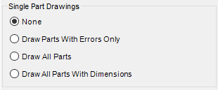
None – No parts are drawn into the parts.dwg file.
Draw Parts with Errors Only – Draws only parts with errors in their G-Code into the parts.dwg file.
Draw All Parts – Draws all parts into the parts.dwg file.
Draw All Parts with Dimensions – Draws all parts into the parts.dwg file with the dimensions set in the Dimension Settings button, dimension the overall part size, routing, sawing, vertical drilling, and horizontal drilling machining operations.
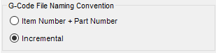
G-Code File Naming Convention
Item Number + Part Number – This naming convention generates more descriptive G-Code file names, but increases the chance for duplicate file names.
Incremental – This naming convention generates a random file name single part G-Code files and ensures that the program creates unique file names.
WMF, DXF Settings
WMF Settings – Properties that control the dimensions for overall part size, routing, sawing, vertical drilling, and horizontal drilling machining operations.DXF Settings – Properties that determine and control how the dimension styles present within a DXF file apply in routing, sawing, vertical drilling, and horizontal drilling machining operations. Changes in dimensions must be made within the DXF template.
Path to DXF Template – Click browse to select the path to the file folder wherein one's DXF template is stored.
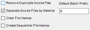
G-Code File Name Options
Remove Duplicate G-Code Files – Compares each G-Code file created for duplicate files. If the program encounters a duplicate G-Code file, all references within the database will match the original file. Removing duplicate G-Code files reduces redundancy and allows a single program for identical parts.
Separate G-Code Files by Material – Creates the G-Code files for nests and single parts in separate folders based on material.
Clear File Names – Clears the default program functionality of assigning file names that match the data specified in the cut parts file, column N, if data exists there. If this checkbox is checked, the program will apply the names specified in the cut parts file. If it is cleared, the program will apply random file names.
Create Sequential File Names – Causes the program to assign file names sequentially instead of randomly.
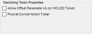
Machining Token Properties
Controls specific machining token properties.
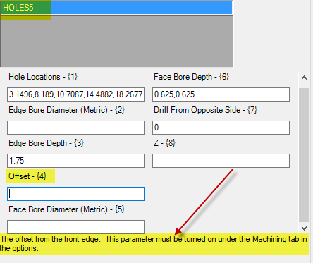
Allow Offset Parameter (4) on HOLES Token - enables parameter (4) of the Holes Token (see Fig. 31)
Pocket Corner Notch Token - sets pocketing for corner notch instead of a cutout.
Related Articles
Configuration Editor: Processing Options
This article provides an overview of the options and settings available on the Processing tab of the Configuration Editor (Options) Interface. For a complete list of available tabs and options visit Overview: Configuration Editor (Options) Interface. ...Overview: Configuration Editor (Options) Interface
The Configuration Editor (Options) Interface for Microvellum Toolbox is accessible from the Toolbox Setup menu. Using the options contained within, you'll configure general system settings, set up the optimization software you use, set up tool files, ...Configuration Editor: Solid Analyzation Options
This article provides an overview of the options and settings available on the Solid Analyzation tab of the Configuration Editor (Options) Interface. For a complete list of available tabs and options visit Overview: Configuration Editor (Options) ...Configuration Editor: General Options
This article provides an overview of the options and settings available on the General tab of the Configuration Editor (Options) Interface. For a complete list of available tabs and options visit Overview: Configuration Editor (Options) Interface. ...Configuration Editor: CAD Options
This article provides an overview of the options and settings available on the CAD tab of the Configuration Editor (Options) Interface. For a complete list of available tabs and options visit Overview: Configuration Editor (Options) Interface. ...
Recent Articles
Microvellum Release Notes | Build 26.1.0723.641
The following release notes apply to Microvellum build 26.1.0723.641. Function UI Update The Function Arguments interface has received a major visual overhaul to improve the usability, clarity, and visibility of several elements. Input fields are now ...Microvellum Release Notes | Build 26.1.0702.641
Dark Mode Fig. 1: The MV Palette in Dark Mode. To enhance the user experience when working within Microvellum, a new Dark Mode setting has been added to the software. Enabling this will apply a dark theme to most interfaces, allowing for a greater ...Microvellum Foundation Library Release Notes | Build 26.0630
Additions: Added new Fixture product Die Wall Advanced. This product takes the legacy Die Wall products to a new level. More features and advanced parametric abilities: Up to five individual unique subassembly segments, widths controlled via ...Microvellum Foundation Library Release Notes | Build 26.0527
The following release notes apply to the Microvellum Foundation Library build 26.0527. Additions Added new features for the Wood Drawer Box to have reduced sides, sub front, or back. Added 3 new global and subassembly prompts: “Wood Drawer Side ...Microvellum Release Notes | Build 26.1.0529.641
The following release notes apply to Microvellum build 26.1.0529.641. BSB Docking Size Fix An issue was reported to be occurring in Microvellum BSB 2026: when adjusting the size of a docked Microvellum palette, users found that the palette would ...